Zero drill completion and production system

a production system and drilling technology, applied in the direction of sealing/packing, fluid removal, borehole/well accessories, etc., can solve the problems of complex and often dangerous prior art procedures for accomplishing these steps, and the absolute volume of cement dispersed into the bore is insignifican

Inactive Publication Date: 2004-05-04
BAKER HUGHES INC
View PDF13 Cites 27 Cited by
  • Summary
  • Abstract
  • Description
  • Claims
  • Application Information

AI Technical Summary

Problems solved by technology

Consequently, prior art procedures for accomplishing these steps are complex and often dangerous.
Although the residual cement column is discharged into the production zone bore, the absolute volume of cement dispersed into the bore is insignificant.

Method used


Image

  • Zero drill completion and production system
  • Zero drill completion and production system
  • Zero drill completion and production system

Examples


Embodiment Construction

following hereafter refers to the several figures of the drawings wherein like reference characters in the several figures relates to the same or similar elements throughout the several figures and:

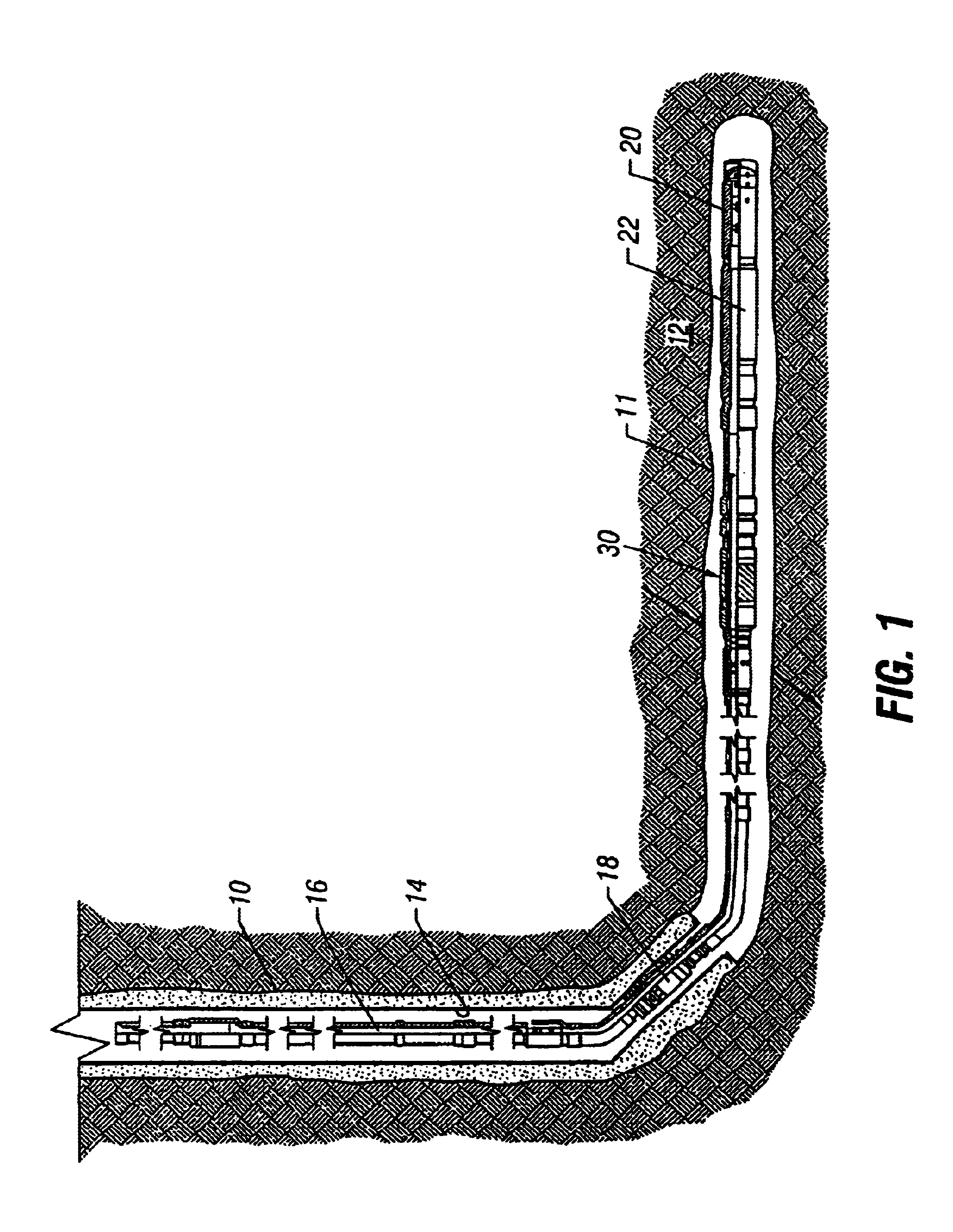
FIG. 1 is a schematic well having the present invention in place for completion and production;

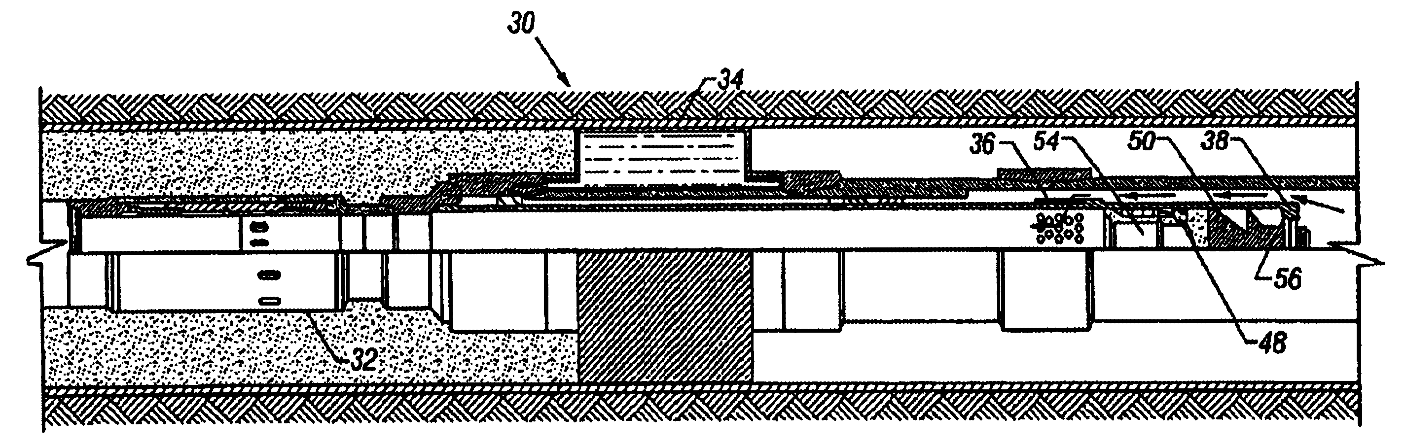
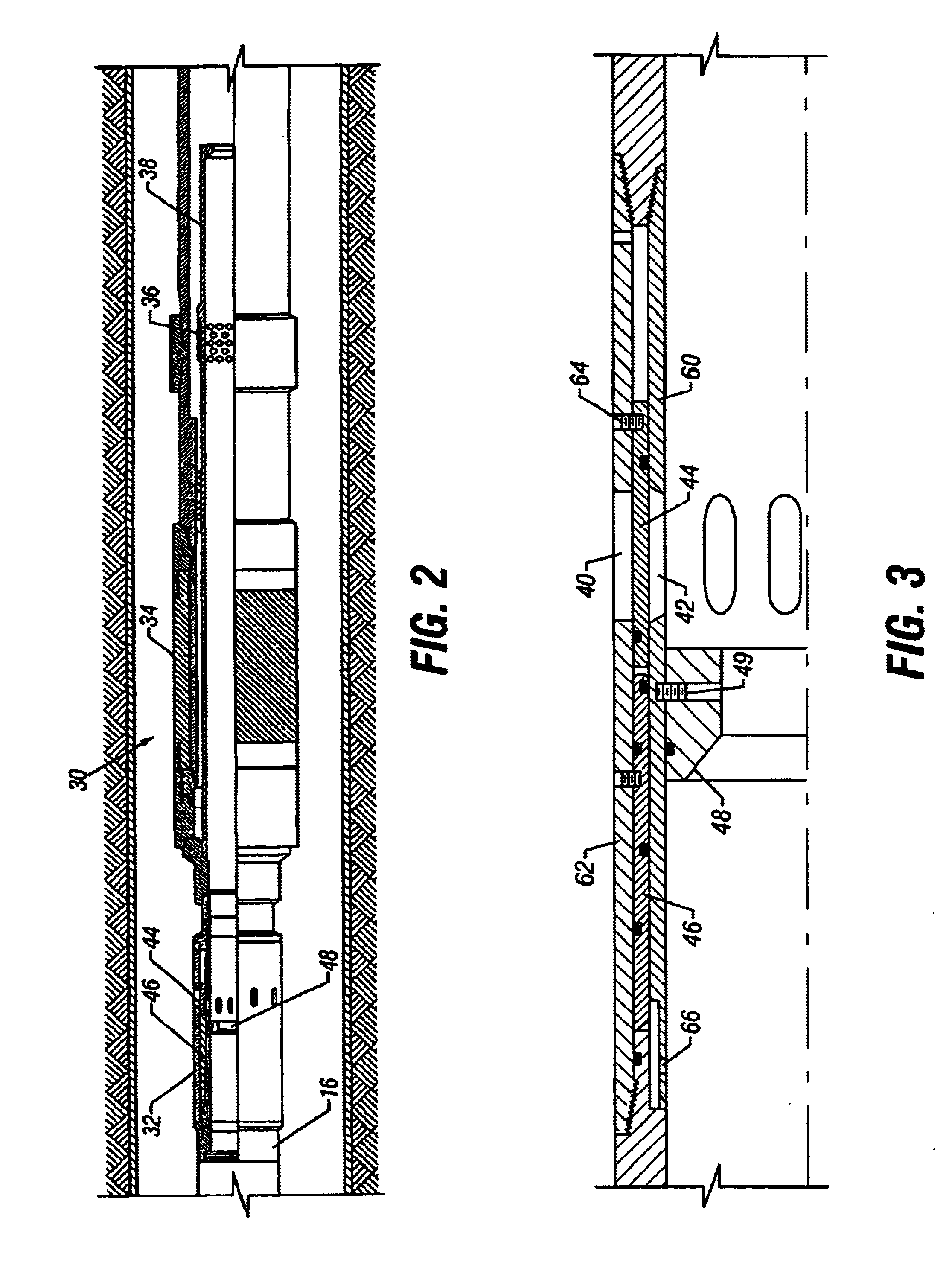
FIG. 2 is a partial section of the present well completion tool assembly in the run-in condition;

FIG. 3 is a partial section detail of the cementing valve run-in setting;

FIG. 4 is a partial section of the present well completion tool assembly in the packer inflation condition;

FIG. 5 is a partial section of a closed, pressure actuated cementing valve;

FIG. 6 is a partial section detail of the open cementing valve;

FIG. 7 is a partial section of the present well completion tool assembly in the annulus cementing condition;

FIG. 8 is a partial section of the present well completion tool assembly in the cement termination condition;

FIG. 9 is a partial section detail of the closed cementing valve;

FIG. 10...


PUM


Abstract

Apparatus for a one trip completion of fluid production wells. A completion tool string includes a pressure activated cementing valve, an external casing packer, a pressure activated production valve, an opening plug and a plug landing collar and a closing plug and seat. This tool series is assembled near the end of a production tube string upstream of the well production screen.

Description

1. Field of the InventionThe present invention relates to petroleum production wells. More particularly, the invention relates to well completion and production methods and apparatus.2. Description of the Prior ArtThe process and structure by which a petroleum production well is prepared for production involves the steps of sealing the production zone from contamination and securing production flow tubing within the well borehole. These production zones are thousands of feet below the earth's surface. Consequently, prior art procedures for accomplishing these steps are complex and often dangerous. Any procedural or equipment improvements that eliminate a downhole "trip", is usually a welcomed improvement.Following the prior art, production tube setting and opening are separate "trip" events. After a well casing is secured by cementing, a production string is then positioned where desired within the borehole and the necessary sealing packers set. In some cases, the packers are set by...

Claims


Application Information

Patent Timeline
Patent Type & Authority Patents(United States)
IPC IPC(8): E21B33/13E21B34/00E21B34/06E21B21/00E21B21/10E21B33/14E21B33/16
CPCE21B21/103E21B33/14E21B33/16E21B34/06E21B34/063
Inventor VINCENT, RAYGESTE, STEVE
Owner BAKER HUGHES INC
Why Eureka
Try Eureka