Side feed wheel assembly for wood chipper

a feed wheel and wood chipper technology, applied in the field of wood chipper, can solve the problems of time-consuming and undesired, and the infeed is not connected to the primary feed wheel assembly,

Inactive Publication Date: 2004-05-04
BANDIT IND
View PDF104 Cites 25 Cited by
  • Summary
  • Abstract
  • Description
  • Claims
  • Application Information

AI Technical Summary

Problems solved by technology

Although this primary feed wheel assembly has worked well, it is known that the wood material fed to the primary feed wheel assembly tends to slide to a side of the infeed hopper.
This may result in plugging of the infeed to the primary

Method used


Image

  • Side feed wheel assembly for wood chipper
  • Side feed wheel assembly for wood chipper
  • Side feed wheel assembly for wood chipper

Examples


Embodiment Construction

)

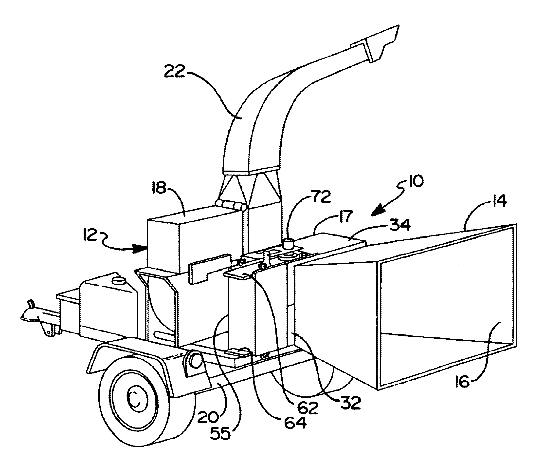
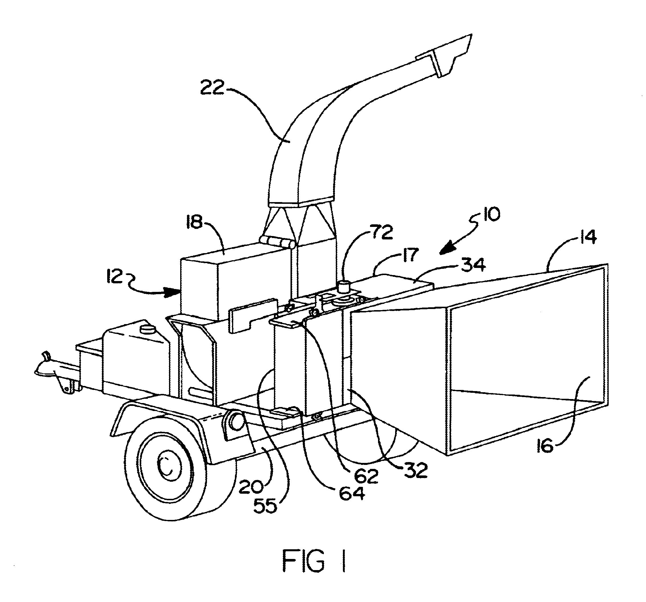
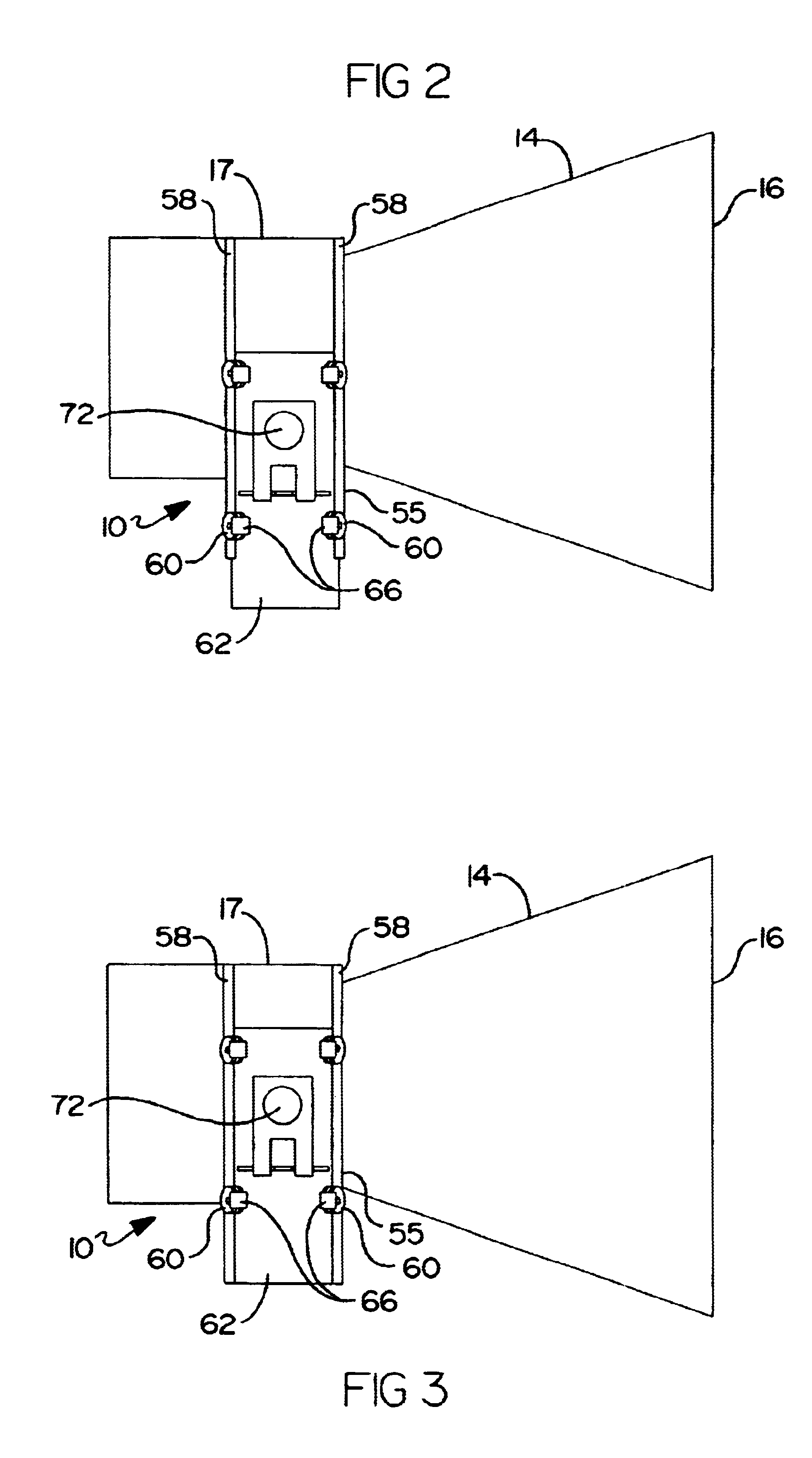
Referring now to the drawings and in particular FIGS. 1 through 6B, one embodiment of a side feed wheel assembly 10, according to the present invention, is shown for a wood chipper, generally indicated at 12. The wood chipper 12 includes an infeed hopper assembly 14 having an inlet 16 to allow wood material to enter the wood chipper 12. The wood chipper 12 also includes a primary feed wheel assembly 17 disposed between and adjacent to the infeed hopper assembly 14 and a cutting assembly 18 for rotation about a horizontal axis adjacent to the primary feed wheel assembly 17. The primary feed wheel assembly 17 is used for pulling and pushing the wood material from the infeed hopper assembly 14 to the cutting assembly 18. The cutting assembly 18 includes a rotatable disc or drum (not shown) having a plurality of blades (not shown) operatively connected to the disc or drum for chipping the wood material. The side feed wheel assembly 10 is used to push or feed wood material to the primar...


PUM


Abstract

A side feed wheel assembly for a wood chipper includes at least one side feed wheel adapted to be disposed adjacent at least one primary feed wheel of the wood chipper. The side feed wheel assembly also includes a mechanism for moving the at least one side feed wheel transversely relative to the at least one primary feed wheel to feed wood material to the at least one primary feed wheel of the wood chipper.

Description

1. Field of the InventionThe present invention relates generally to wood chippers and, more particularly, to a side feed wheel assembly for a wood chipper.2. Description of the Related ArtIt is known to provide a wood chipper for chipping wood such as brush, branches, and the like to produce wood chips. An example of such a wood chipper is disclosed in U.S. Pat. No. 5,988,539 to Morey. In this patent, the wood chipper includes an infeed hopper, primary feed wheel assembly, and a cutting assembly having a rotatable disc or drum with at least one knife or blade for chipping the wood entering the wood chipper and reducing it to wood chips. Typically, the primary feed wheel assembly includes a stationary lower primary feed wheel connected to a lower housing and a movable upper primary feed wheel connected to an upper housing movable relative to the lower housing for allowing wood to enter the cutting assembly. The primary feed wheel assembly may include a spring interconnecting the uppe...

Claims


Application Information

Patent Timeline
IPC IPC(8): A01G3/00B02C18/06B02C18/22
CPCA01G3/002B02C18/2283
Inventor MOREY, MICHAEL DWAIN
Owner BANDIT IND
Why Eureka
Try Eureka