Endoprosthesis for a shoulder joint

Inactive Publication Date: 2004-06-15
BAHLER OLGA MARIA
View PDF39 Cites 142 Cited by
  • Summary
  • Abstract
  • Description
  • Claims
  • Application Information

AI Technical Summary

Benefits of technology

It is therefore the object of the invention to propose an endoprosthesis for a shoulder joint in which the advantages of the prior art cited are preserved, while the aforementioned disadvantages of ball joints are avoided. In particular, the greatest possible forces of friction should be attained between the individual parts that are displaceable and rotatable counter to one another. Moreover, it should be possible to define the direction and position of the joint axis independently of one another. Compared to the prior art, the calibration of directi

Problems solved by technology

A disadvantage of this prosthesis is that the cap must be precisely placed in every direction before it can be fixed in this position.
Furthermore, the grub screws must be tightened before the prosthesis is inserted, because afterward they are no longer accessible.
This requires multiple test manipulations of the arm being operated on and corrections to the cut face of the bone during the operation and makes a correction of the alignment after implantation has been completed impossible.
A disadvantage of this prosthesis, however, is that the spherical surfaces must be produced exactly concentrically, which is complicated and expe

Method used


Image

  • Endoprosthesis for a shoulder joint
  • Endoprosthesis for a shoulder joint
  • Endoprosthesis for a shoulder joint

Examples


Example

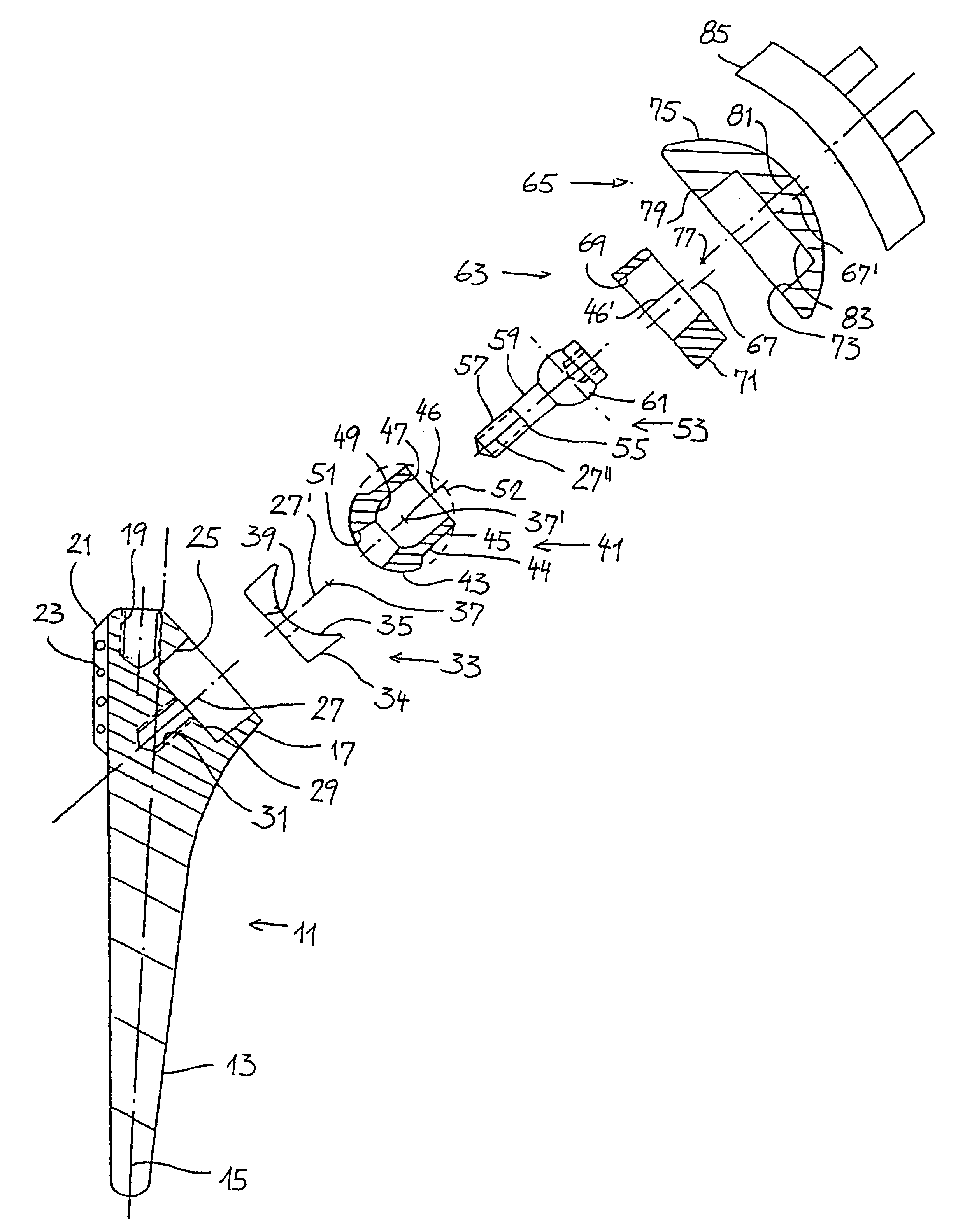
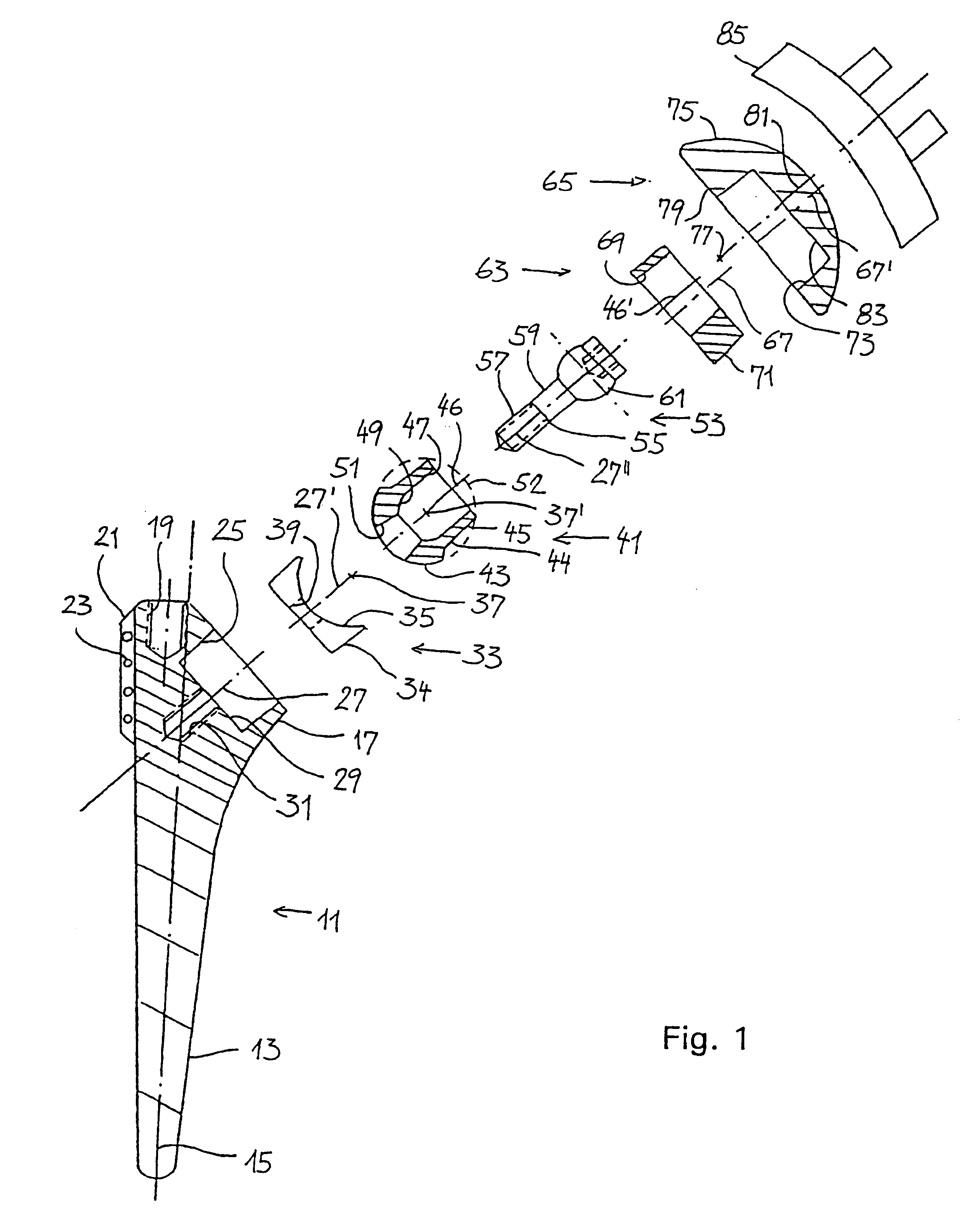
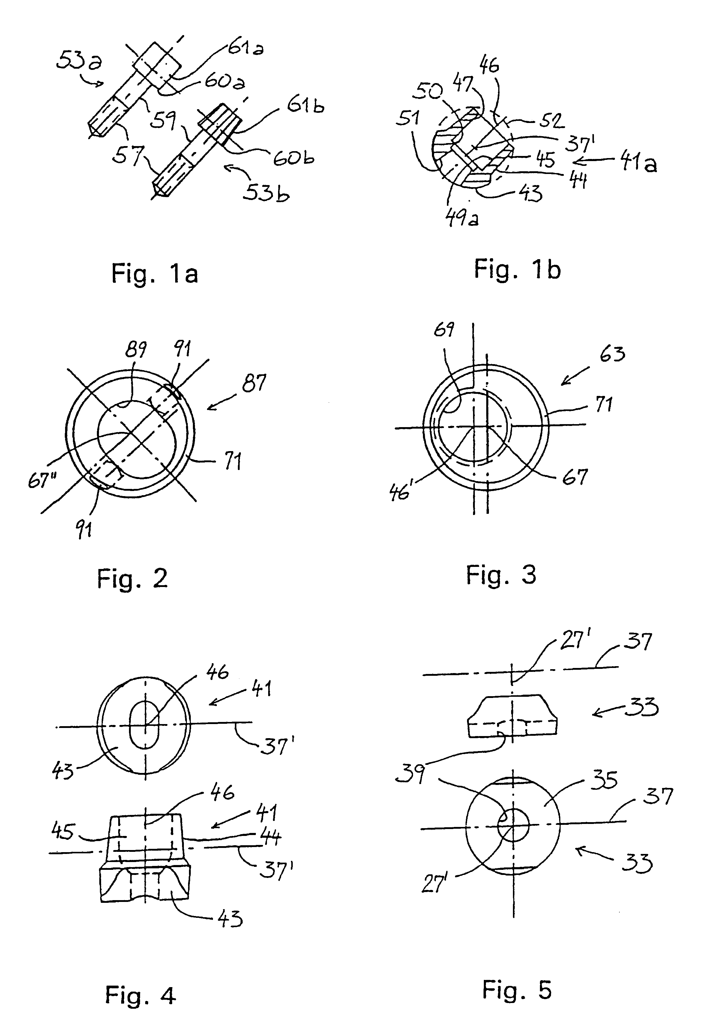
This object is attained by disposing a rotating piece between the shaft part and the directional piece, the rotating piece being rotatable relative to the shaft part and a first axis, and the directional piece is supported rotatably relative to the rotating piece about a second axis, and this second axis extends transversely to the first axis and transversely to the directional axis; contact faces between the shaft part and the rotating piece, on the one hand, and between the rotating piece and the directional piece on the other each allow only a relative motion between the shaft part and rotating piece, and the rotating piece and directional piece, respectively, about the respective common first and second axis, as a center of rotation.

As a result of this separation of the pivoting motion of the directional piece into two pivoting motions about two axes that cross one another, the full range of motion that a ball joint offers is preserved, yet in comparison to a ball joint the risk...


PUM


Abstract

The invention relates to an endoprosthesis for a shoulder joint comprising a rotating piece which is connected to a shaft part such that it can rotate around a first axis, and comprising an axial directional piece which is connected to said rotating piece such that it can rotate around a second axis. Both pivotal axes are perpendicular to one another and the second axis is perpendicular to the axis of the directional piece. The spherical cap is either placed directly on the directional piece, or an eccentric ring or an oblong hole ring which supports the spherical cap is provided between the spherical cap and directional piece. Two or more eccentric rings can also be provided. The spherical cap can comprise a centric or eccentric conical surface. The direction of the first axis can be selected in a relatively free manner.

Description

The invention relates to an endoprosthesis for a shoulder joint as generically defined by the preamble to claim 1.PRIOR ARTFrom European Patent Disclosure EP 0 712 617, a shoulder joint prosthesis is known whose shaft part has an indentation with a hemispherical bottom in its metaphysial end, into which indentation a ball is introduced. This ball has a central continuous bore and a slot that communicates with the bore over its entire length and splits the ball ring, making it C-shaped. A stem connected to the cap is inserted into the bore. Grub screws are provided in the shaft part, in order to immobilize the ball in the indentation in a selectable angular position and to deform the ball ring and thereby firmly clamp the stem in it.A disadvantage of this prosthesis is that the cap must be precisely placed in every direction before it can be fixed in this position. To that end, it must be held in this position by a surgeon while the grub screws are being tightened forcefully. Further...

Claims


Application Information

Patent Timeline
IPC IPC(8): A61F2/30A61F2/40A61F2/00A61F2/02A61F2/46
CPCA61F2/4014A61F2/40A61F2/4059A61F2/4081A61F2/4612A61F2002/30143A61F2002/30329A61F2002/30332A61F2002/30341A61F2002/30378A61F2002/30405A61F2002/30434A61F2002/30443A61F2002/30495A61F2002/30507A61F2002/3051A61F2002/30512A61F2002/30537A61F2002/30538A61F2002/3054A61F2002/3055A61F2002/30604A61F2002/30626A61F2002/30632A61F2002/30777A61F2002/30785A61F2002/30795A61F2002/30797A61F2002/30884A61F2002/30902A61F2002/4018A61F2002/4029A61F2002/4037A61F2002/404A61F2002/4044A61F2002/4062A61F2002/4619A61F2220/0025A61F2220/0033A61F2220/0041A61F2230/0017A61F2250/0004A61F2250/0006A61F2250/0007A61F2002/30339A61F2002/30433A61F2002/30624
Inventor BAHLER, ANDRE
Owner BAHLER OLGA MARIA
Why Eureka
Try Eureka