High speed pick and place apparatus

a pick-and-place, high-speed technology, applied in the direction of mechanical control devices, instruments, process and machine control, etc., can solve the problems of high speed operation, high degree of accuracy, and difficulty

Inactive Publication Date: 2004-07-06
ASM ASSEMBLY AUTOMATION LTD
View PDF15 Cites 25 Cited by
  • Summary
  • Abstract
  • Description
  • Claims
  • Application Information

AI Technical Summary

Problems solved by technology

A difficulty arises, however, with high speed operation.
This sudden stopping of the bond arm causes substantial vibrations in the bond arm that result in a placement error.
This is particularly problematic when the bond arm has been moved to transfer a die from the pick location to the place location where a very high degree of accuracy is required.
In practice, the placement and subsequent bonding operations cannot be performed until the vibration of the bonding arm caused by the sudden stopping of the rotary movement has died away.
In other words, any gains in operational speed from high speed rotary movement of the pick and place apparatus are, at least to a degree, lost by the fact that the consequential vibrations must be allowed to die away before the placement and bonding operations can be performed.

Method used


Image

  • High speed pick and place apparatus
  • High speed pick and place apparatus
  • High speed pick and place apparatus

Examples


Embodiment Construction

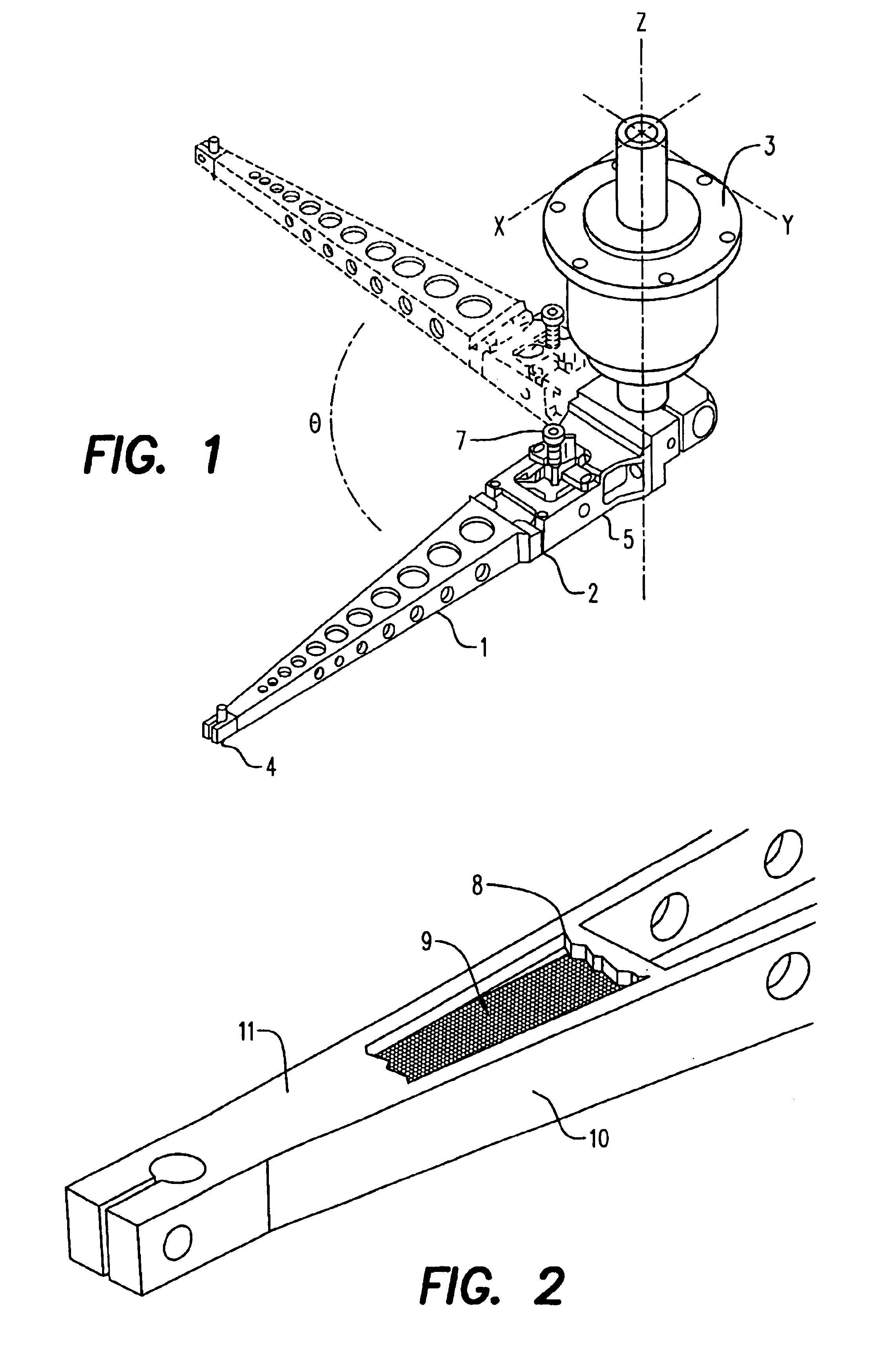
As described above, FIG. 1 shows a basic type of pick and place apparatus, and to which the present invention may be applied. In particular the apparatus comprises a pick and place member in the form of a bond arm 1 adapted for rotation about a Z-axis, and additionally vertical movement along said Z-axis. The bond arm may be divided by pivot joint 2 to provide a rear bond arm portion 5. The main part of the bond arm 1 can swing about pivot joint 5 so that a pick tool can move in the Z-direction. Pick, placement and bonding operations involve movement in the Z-direction, either using the actuator 3 or by pivoting movement of the main part of the bond arm 1 about pivot joint 5. Transfer of dies, however, from a pick location to the desired place location, involves a rotary movement about the Z-axis through an angle .theta..

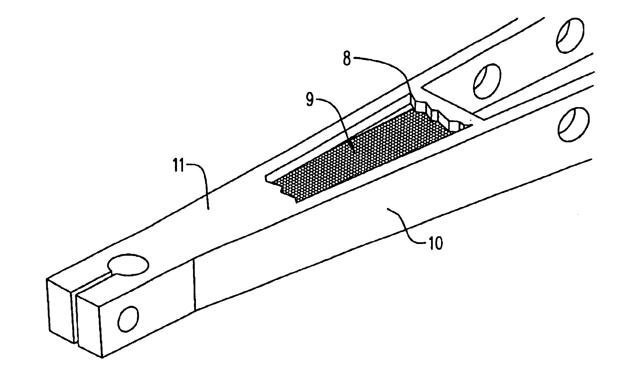
FIG. 2 shows in detail a portion of the end of the bond arm 1 distal from the actuator 3, and therefore at the most remote point from the Z-axis. As can be seen fro...


PUM


Abstract

A pick and place apparatus comprises a bond arm adapted for rotation about an axis between a pick location and a place location. The bond arm is formed with a cavity at an end of the arm remote from the axis, within which cavity are located a plurality of damping particles for damping unwanted vibrations of the bond arm. The particles may be irregular tungsten granules with a diameter between 0.3 and 1.2 mm and a filling ratio of about 75%.

Description

This invention relates to a pick and place apparatus, in particular to such an apparatus for use in a die attachment operation in semiconductor manufacturing processes, and more particularly still is directed to such an apparatus that is capable of operating at high speed and with high precision.Pick and place apparatus are used in a number of operations within semiconductor manufacturing and assembly processes. As the name implies, a pick and place apparatus functions to pick a component from one location, and then place it in a second location.One example of such apparatus is used in a die attachment operation. In such an operation a pick and place apparatus is used to pick a die from a delivery mechanism, and then transfer the die to a desired location on, for example, a printed circuit board and place the die on the board. The apparatus may also carry out a bonding operation.It will be appreciated that the speed of the die attachment operation is dependent on the speed with whic...

Claims


Application Information

Patent Timeline
Patent Type & Authority Patents(United States)
IPC IPC(8): B65G47/90H01L21/00
CPCB65G47/904H01L21/67121Y10T74/20305
Inventor CHOY, PING KONGLIU, CHOU KEELAIO, WEI HSINWANG, YU
Owner ASM ASSEMBLY AUTOMATION LTD
Why Eureka
Try Eureka