
Apparatus for holding a contact image sensor in a scanning system

a technology for contact image sensors and scanning systems, applied in electrical apparatus, pictoral communication, etc., can solve the problems of inability to accept the quality of captured images by cis, the depth of scanning field of cis is far short, and the prior known scanning device is not suitable for the present marketing needs

Inactive Publication Date: 2004-07-13
TRANSPACIFIC OPTICS
View PDF3 Cites 37 Cited by
  • Summary
  • Abstract
  • Description
  • Claims
  • Application Information

AI Technical Summary

Problems solved by technology

However, the prior known scanning device is not suitable to the present marketing needs.
However, since the depth of scanning field of CIS is far short than the depth of scanning field of CCD.
If the CIS is unable to closely adjacent to the document plate, the quality of captured images by CIS is not accepted.
Therefore, it is very important and causing a big problem to make sure CIS closely adjacent the document plate and moving smoothly.
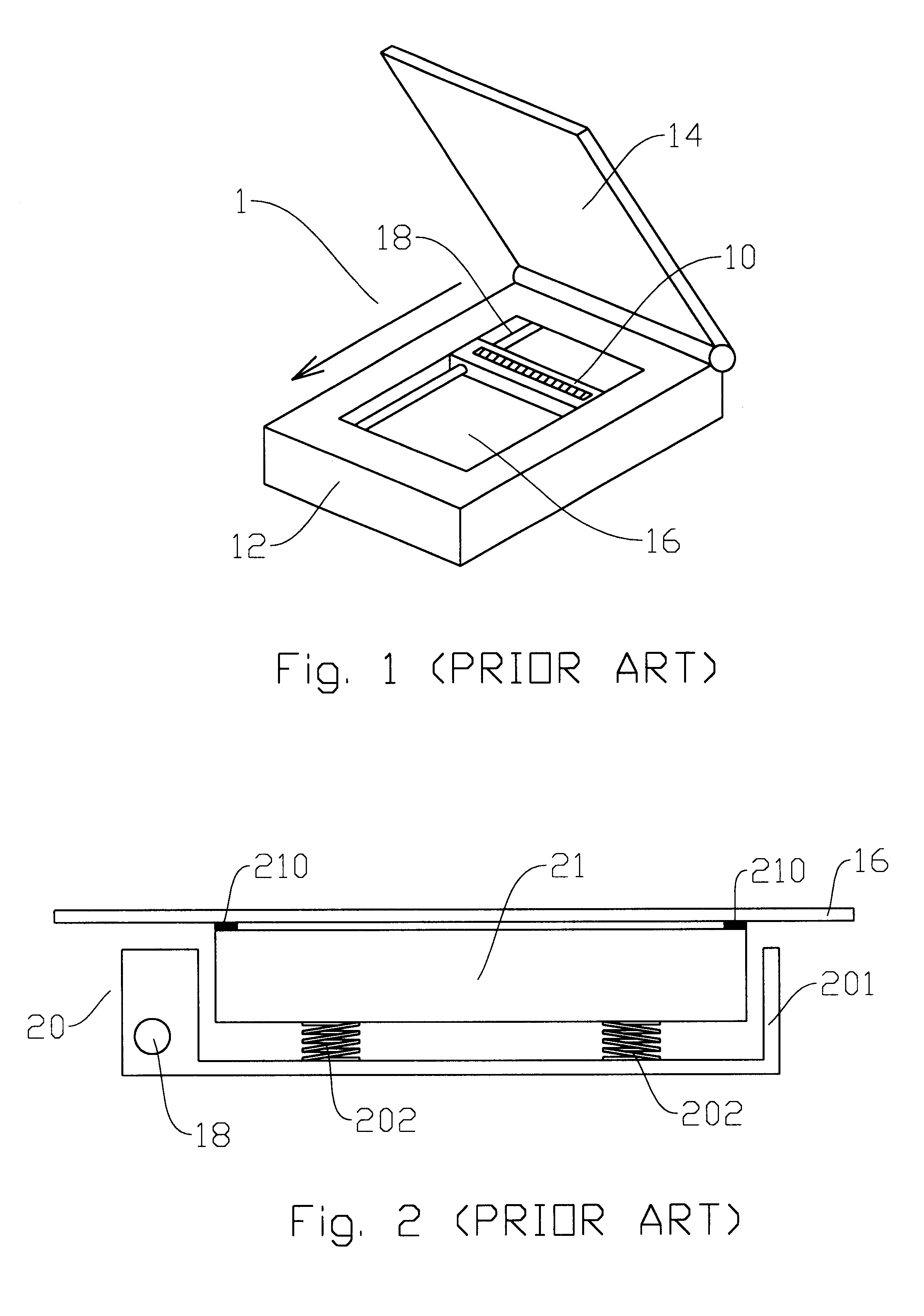
Nevertheless, in the above known solution, since springs are set between the document plate and CIS, it would cause CIS getting jammed if the springs provide unequal forces to CIS.

Method used


Image

  • Apparatus for holding a contact image sensor in a scanning system
  • Apparatus for holding a contact image sensor in a scanning system
  • Apparatus for holding a contact image sensor in a scanning system

Examples


Embodiment Construction

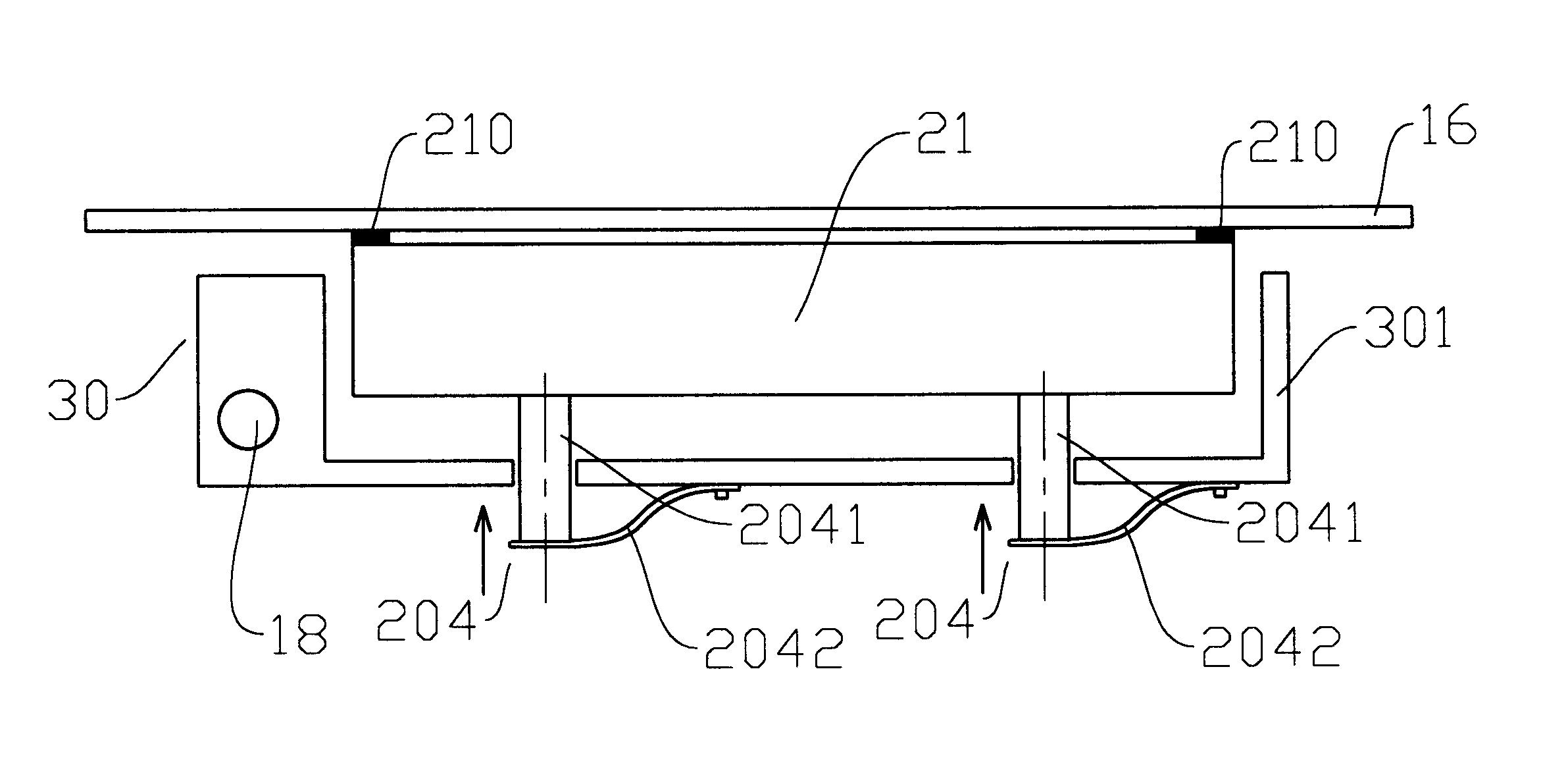
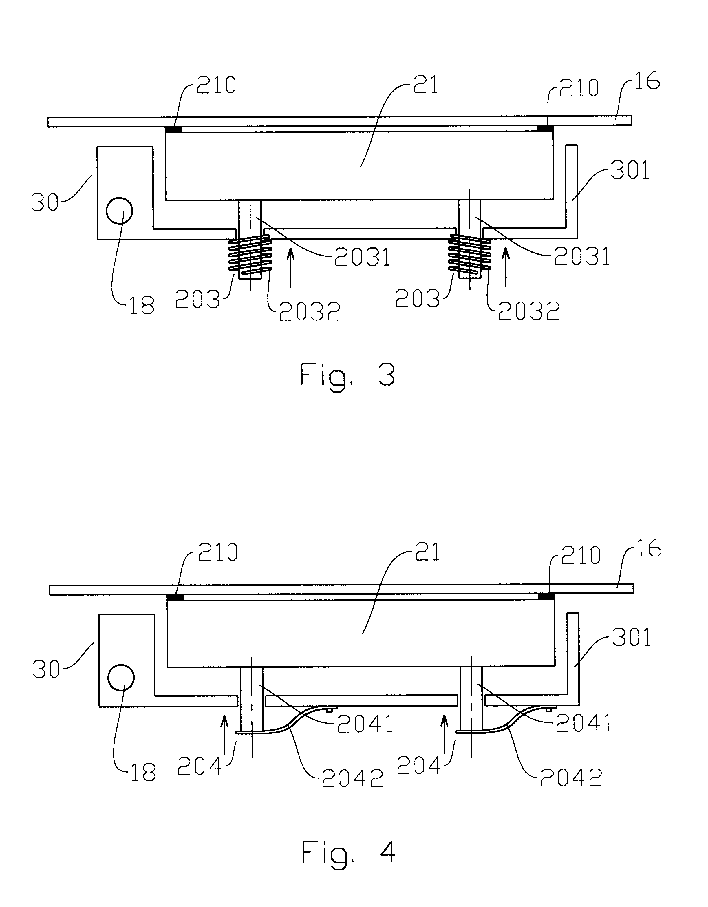
Please refer to FIG. 3. FIG. 3 shows the cross section of the first embodiment of CIS holding device of the present invention. The CIS holding device 30 includes a holder 301 and a elastic device 203. The holder 301 contains an opening for receiving the CIS 21. The elastic device 203 includes at least a supporting shafts 2031 and springs 2032. The supporting shaft 2031 is set through and beneath the holder 301. The supporting shaft 2031 further contacts the CIS 21 for supporting the CIS 21. One port of the spring 2031 is connected to supporting shaft 2031. The opposite port of the spring 2031 is mounted on the holder 301. In this case, the spring 2032 is able to provide a recovering force to the CIS 21 upwardly, shown as the arrow direction. By the recovering force, CIS 21 is thus able to close the document plate 16. When the CIS holding device 30 is driven along the driving rod 18 to capture the image of document, CIS 21 can stay close to bottom surface of the document plate 16 sin...


PUM


Abstract

An apparatus for holding a contact image sensor of a scanning system includes a supporting shaft and an elastic element. The supporting shaft is set through a holder and contact the contact image sensor. The elastic element contains a spring. The spring is positioned outside the holder and provides a force to the supporting shaft for pushing the contact image sensor upwardly. In this case, the contact image sensor stays close to a document plate to conduct scanning processes. Since the spring is outside the holder, the variation of holder due to manufacturing would not affect the force from the spring. Thus balanced forces are generated by the springs, further avoiding the situation of the contact image sensor jammed during scanning processes.

Description

1. Field of the InventionThe present invention generally relates to a CIS (Contact Image Sensor) holder for providing a balanced elastic force to ensure CIS being adjacent to a scanning plate and maintaining a fixed depth of scanning field.2. Background DescriptionScanning devices have been broadly employed to input images. Especially when the personal computer is popular, the scanning device is able to scan a document and thus transform to a digitalized image format. Users can therefore edit, make copies and / or store in a storage device.Prior known scanning device 1 is shown in FIG. 1. The scanning device 1 includes a body 12, a cover 14, a scanning module 10, a driving rod 18 and a document plate 16. The scanning module 10 is positioned below the document plate 16 and coupled with the driving rod 18. The scanning module 10 is able to move along the driving rod 18. According to the operation of the prior known scanning device, firstly, a document (not shown in the Figures) is place...

Claims


Application Information

Patent Timeline
Patent Type & Authority Patents(United States)
IPC IPC(8): H04N1/04H04N1/10H04N1/193H04N1/191
CPCH04N1/04H04N1/1017H04N1/193H04N2201/0446H04N2201/0456
Inventor KAO, WILL
Owner TRANSPACIFIC OPTICS
Learn More