
Ramp latching mechanism

a latching mechanism and latching technology, applied in the direction of roofs, ways, transportation items, etc., can solve the problems of increasing the lading per truck, reducing the effective ratio of railcar weight to lading weight, and reducing the slack action along the train

Inactive Publication Date: 2004-07-20
WESTINGHOUSE AIR BRAKE TECH CORP
View PDF11 Cites 15 Cited by
  • Summary
  • Abstract
  • Description
  • Claims
  • Application Information

AI Technical Summary

Benefits of technology

The mechanism allows for quick and secure alignment of ramps, reducing loading time and ensuring safety by preventing inadvertent lowering of the ramp, thus enhancing the efficiency and safety of intermodal train loading processes.

Problems solved by technology

Articulated railroad cars are often able to carry the same number of highway trailers as coupled individual cars, but have fewer rail car trucks, thus increasing the lading per truck and reducing the effective ratio of the railcar weight to lading weight, while also reducing the slack action along the train consist in service.
At present, time is often wasted aligning the ramps.
This requires very large and expensive equipment, however, and can be done only with reinforced trailers.
A large portion of existing highway trailers cannot be handled in this manner.

Method used


Image

  • Ramp latching mechanism
  • Ramp latching mechanism
  • Ramp latching mechanism

Examples


Embodiment Construction

, particularly, when such description is taken in conjunction with the attached drawing figures and the appended claims.

DESCRIPTION OF THE DRAWING

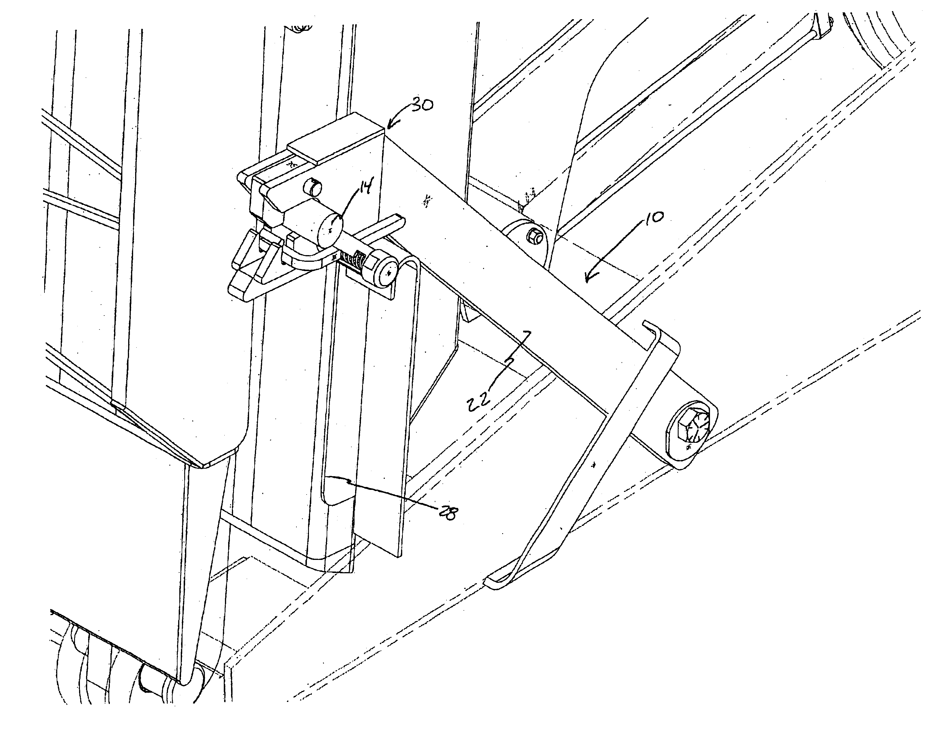
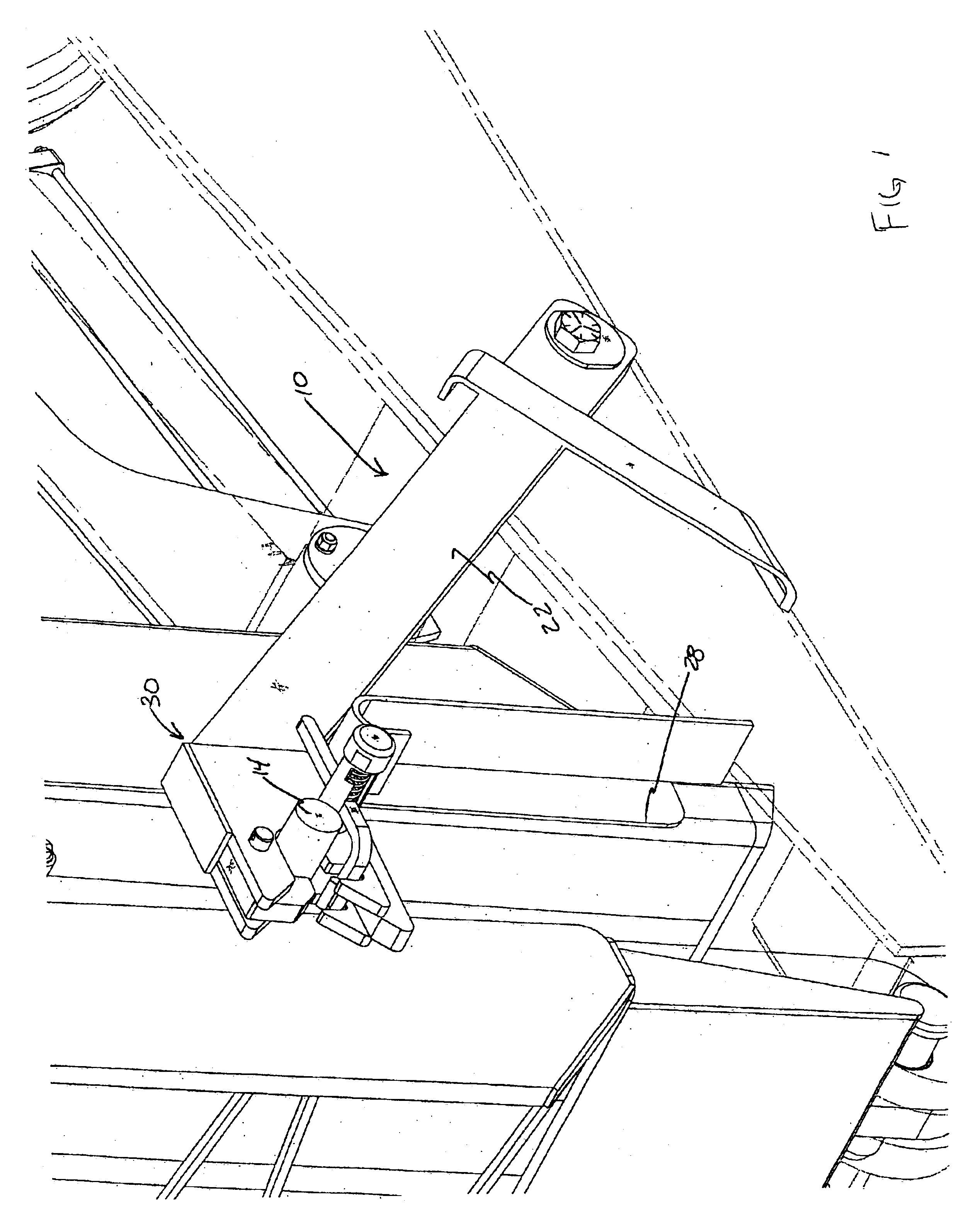
FIG. 1 is a perspective view of the entire latch mechanism as mounted on the ramp style railcar.

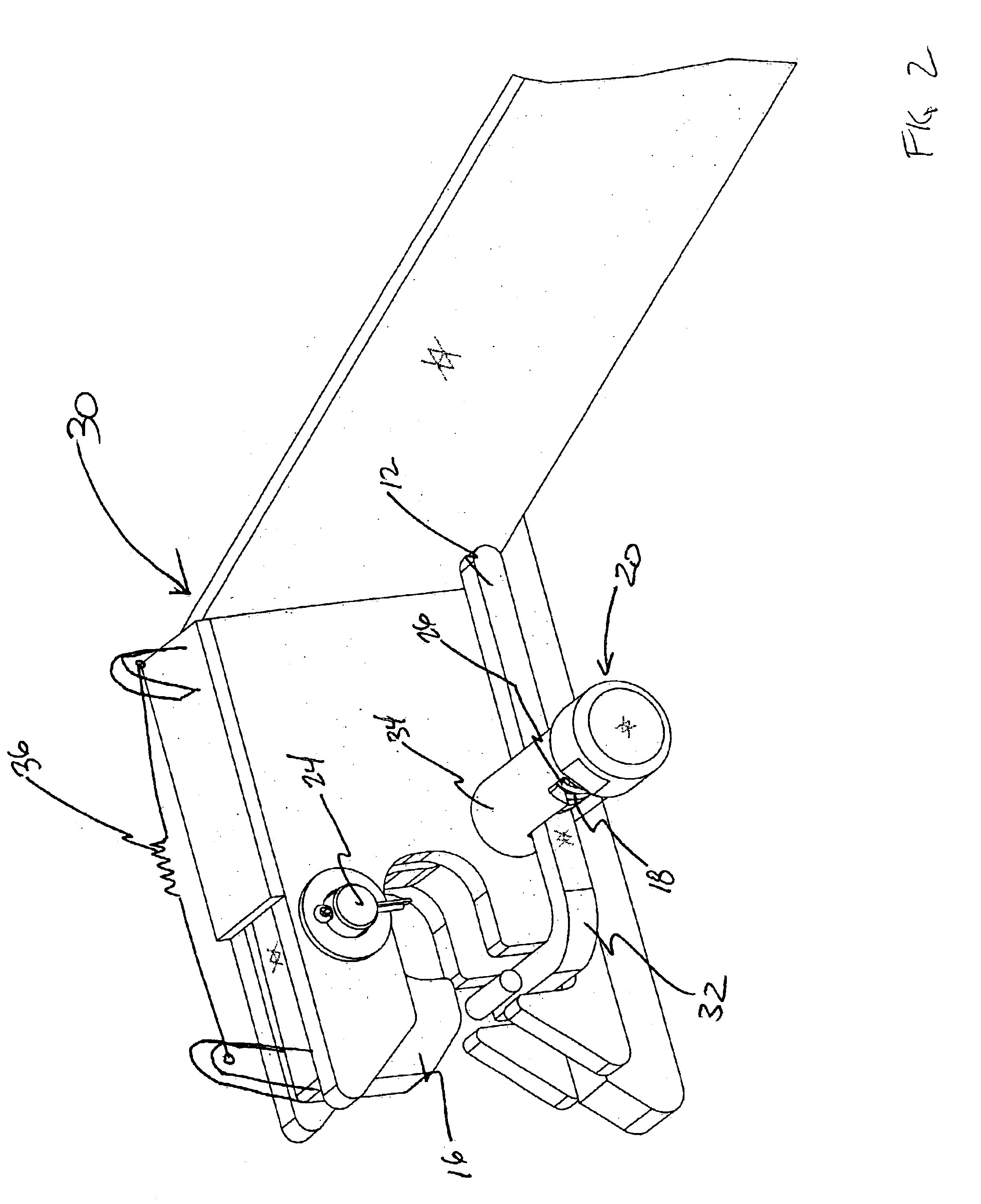
FIG. 2 is a more detailed view of the head of the latch mechanism.

It can be seen from the above discussion that it would be highly advantageous to have a foldable ramp that is permanently fixed to and carried on one end of a multi-platform railcar. Such a ramp may be raised to accommodate train operation and lowered to accommodate efficient loading. With such an arrangement, however, it is very important to assure that the ramp cannot be lowered inadvertently when it is not intended to do so.

Prior to proceeding to a much more detailed description of the present invention, it should be noted that identical components which have identical functions have been identified with identical reference numerals throughout the several views illustrated in t...


PUM


Abstract

A latching mechanism for use with a raisable and lowerable folding ramp having a bridge section and a toe section, such ramp being carried on one end of a railway car. The latching mechanism comprises an arm-like member pivotally connected at one end thereof to a predetermined structure of such railway car and a latch means attached to and extending outwardly from one of the bridge section and toe section of such folding ramp. A latching head portion is disposed at a radially opposed end of such arm-like member, and the latching head portion including a means for securing the latch means. A rotatable latching member is disposed in the latching head portion to engage and lock such latch means when such folding ramp reaches a fully raised position.

Description

The present invention generally relates to a folding ramp carried on the end of a platform railcar for loading and unloading trailers. More particularly, the invention relates to an automatically engaged, manually released safety latch to secure the folding ramp in a raised and stored position for train operation.Railroad cars are often used to transport highway trailers. One method of loading highway trailers or other wheeled vehicles onto railroad cars having decks for carrying vehicles is by what is called circus loading. A ramp is placed at one end of a string of rail car units, and then each vehicle is loaded in sequence by driving them up the ramp and along the decks of the railroad car units. Bridge plates typically span the gaps between successive rail car units. Although circus loading is common for a string of cars, such end-loading can be used for individual rail car units, or multiple rail car units as may be convenient.It is common for portable ramps to be employed to p...

Claims


Application Information

Patent Timeline
Patent Type & Authority Patents(United States)
IPC IPC(8): B60P1/00B61D47/00B61D3/00B61D3/18B60P1/43
CPCB60P1/43B61D3/187B61D47/005
Inventor HART, JAMES E.SICH, GARY M.CARROLL, JOHN B.
Owner WESTINGHOUSE AIR BRAKE TECH CORP
Learn More