Ink jet printer head

a printer head and jet printer technology, applied in printing and other directions, can solve the problems of inability to concentrate the nozzle columns for ejecting ink, inability to obtain predetermined ink ejection, and shortening the service life of the nozzle column,

Inactive Publication Date: 2004-10-26
BROTHER KOGYO KK
View PDF14 Cites 84 Cited by
  • Summary
  • Abstract
  • Description
  • Claims
  • Application Information

AI Technical Summary

Problems solved by technology

This results in cross-talk, wherein undesirable fluctuations in pressure are inevitably generated in the ink in the adjacent pressure chambers 51a, 51c and when ink is again ejected from the same pressure chamber 51a, the fluctuations in pressure overlap so that a predetermined ink ejection cannot be obtained.
HEI-2-4429 and U.S. Pat. No. 5,087,930 achieve a compact size by using lemon-shaped ink pressure chambers, problems arise when the number of nozzles for ejecting ink is increased to produce a color ink jet head.
For example, it is impossible to concentrate the nozzle columns for ejecting ink.
However, a certain amount of time is required from when voltage is first applied to drive a piezoelectric element to when the voltage reaches a predetermined voltage required to deform the piezoelectric element.
If rising-edge time of the voltage is longer than the time required for the pressure wave to propagate once across the pressure chamber, then the piezoelectric actuator cannot be driven efficiently, which defeats the benefit of making the pressure chamber shorter.
Further, if the distance from the ink supply port and the ink ejection nozzles in the pressure chambers is shortened excessively in order to increase the density of pressure chamber columns, the actuators, such as piezoelectric elements, cannot deform into the pressure chambers by an amount sufficient to properly eject droplets.
Cross talk is a problem with these arrangements because of these confronting edges.

Method used


Image

  • Ink jet printer head
  • Ink jet printer head
  • Ink jet printer head

Examples


first embodiment

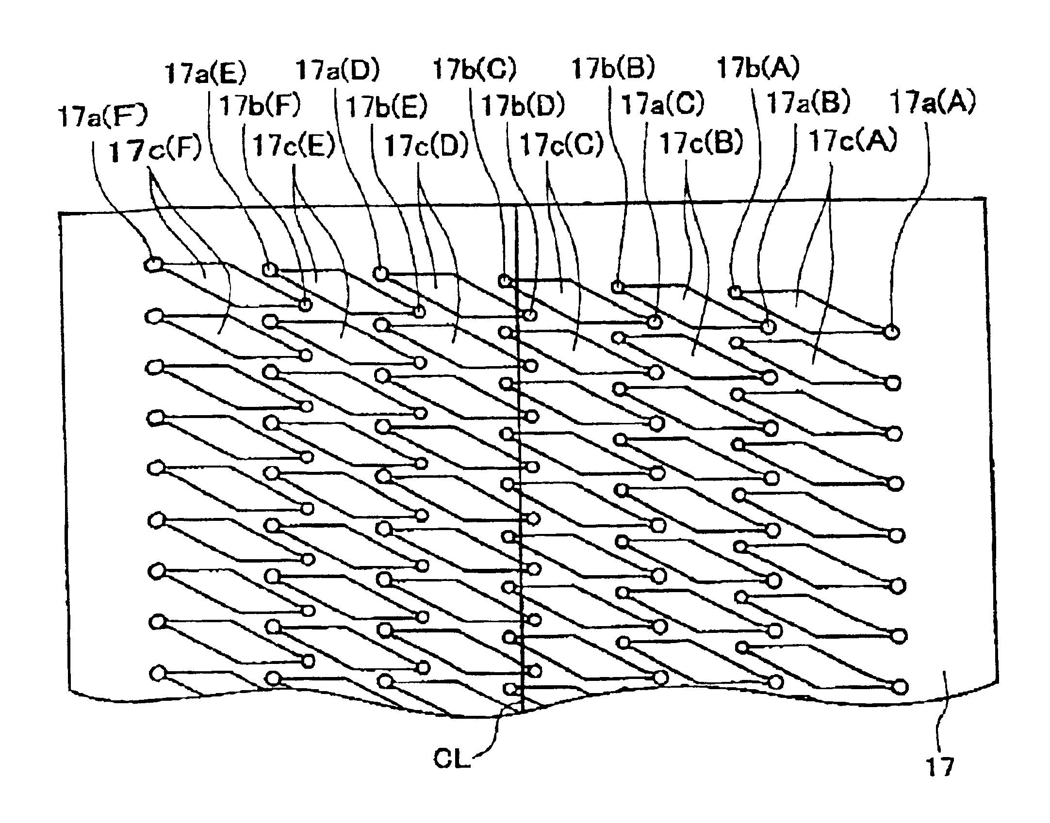
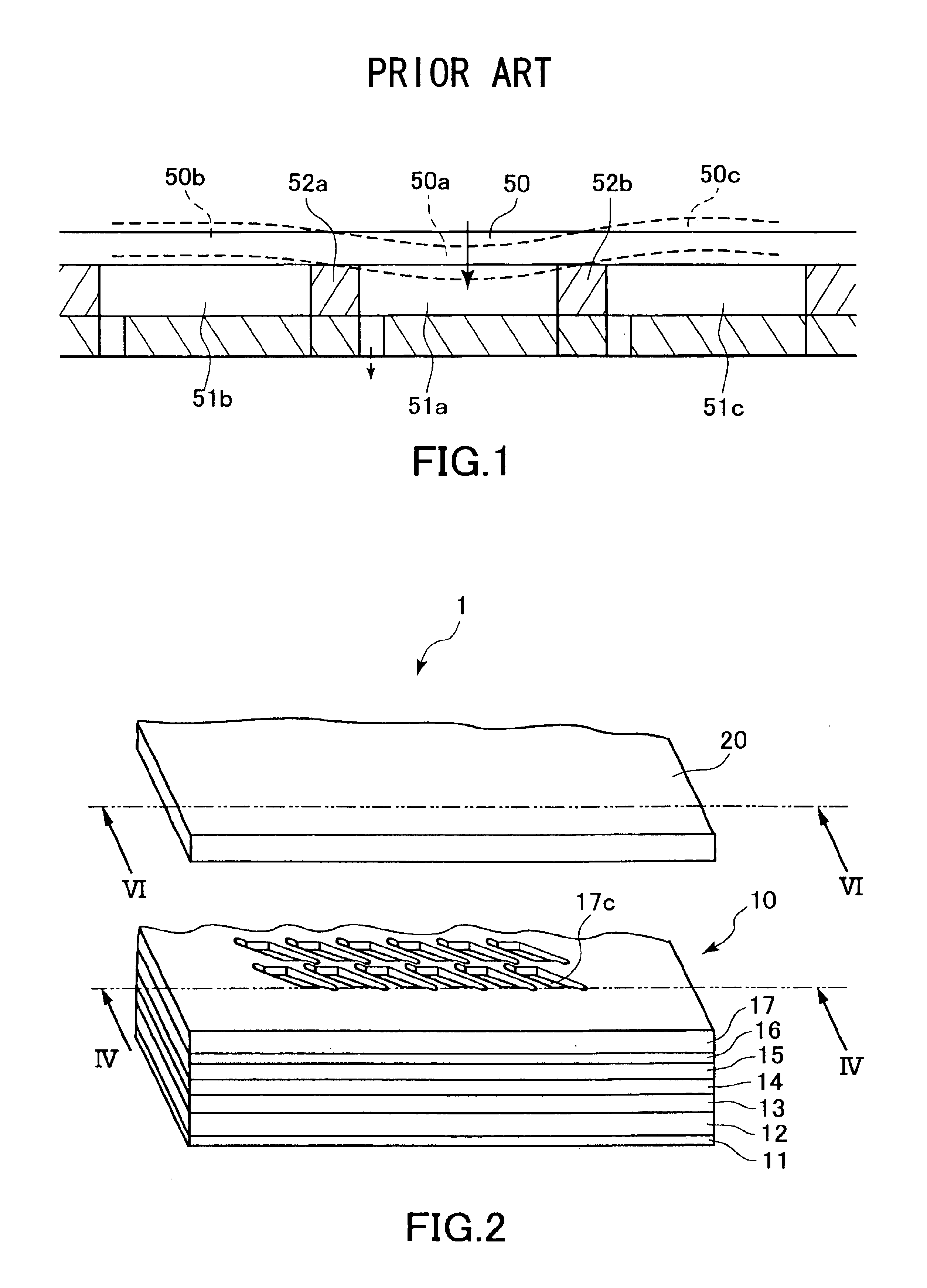
First, an ink jet printer head 1 will be described while referring to FIGS. 2 to 9. As shown in FIG. 2, the ink jet printer head 1 includes a cavity plate 10 and a plate-shaped piezoelectric actuator 20. The cavity plate 10 is configured from laminated metal plates each having a rectangular shape. The actuator 20 is stacked on top of the cavity plate 10. The surface of the cavity plate 10 is formed with plural columns of ink pressure chambers 17c. Each ink pressure chamber 17c has a substantial parallelogram shape with two acute and two obtuse angled portions. This configuration enables providing a plurality of ink pressure chambers without increasing the size of the cavity plate 10.

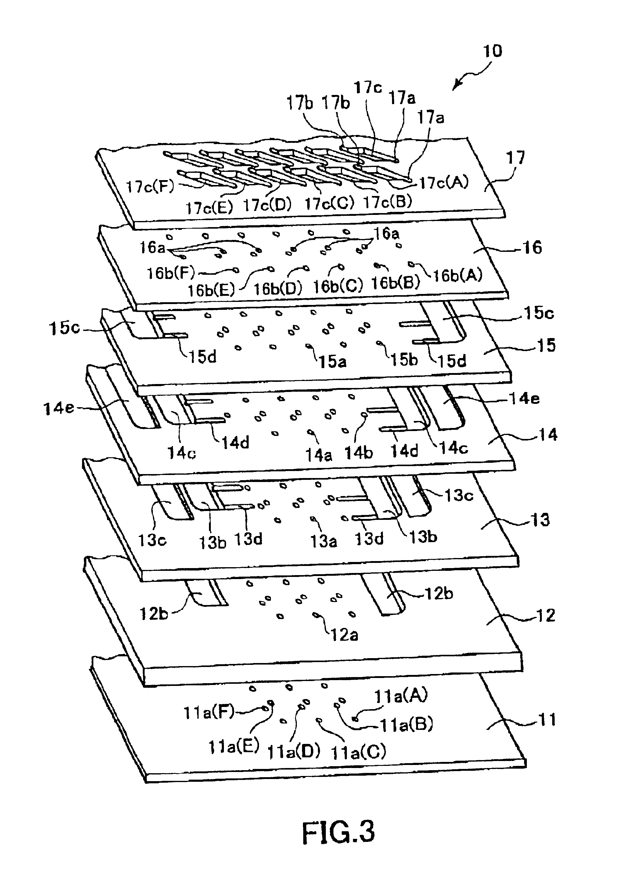
Next, the configuration of the cavity plate 10 will be described while referring to FIGS. 3 and 4. As shown in FIGS. 3 and 4, the cavity plate 10 has a seven-layer configuration made from seven thin layers of rectangular metal plates. The seven layers are, from the bottom up, a nozzle plate 11, a first ...

second embodiment

The actuator unit deforms most into (or away from) the pressure chambers at the principal portions. If the principal portions of an adjacent pressure chamber were aligned in the direction perpendicular to one of the lines a, which is the direction of extension of the perpendicular lines f, f, then as explained with reference to FIG. 1 the deformation of the actuator into (or away from) one of the pressure chambers would also influence adjacent pressure chambers. However, with the configuration of the second embodiment, the portion of the actuator unit that is located at the principal portion of a pressure chamber in one column confronts, that is, in a direction that extends perpendicular to one of the lines a of the pressure chamber, portions of the actuator unit located 1) where the actuator unit is securely fixed to a partition wall 112 that is sandwiched between short lines b, b, of two pressure chambers 111 in an adjacent column and 2) where one of the acute-angle portions c or ...


PUM


Abstract

An ink jet printer head includes a cavity plate and an actuator with the following configuration. The cavity plate is formed with four columns of pressure chambers. Each pressure chamber has a parallelogram shape with two acute-angle portions formed with an ink supply opening and an ink ejection nozzle opening, respectively. The pressure chambers in the center two columns are arranged with the ejection-nozzle sides interposed between each other. The pressure chambers in the outer two columns are arranged with the ejection-nozzle sides interposed between ink-supply sides of the center two columns. The pressure chambers are arranged so that, although the pressure chambers are partially interposed between each other, the principal portion of each pressure chamber in one column is shifted out of alignment from principal portions of pressure chambers in adjacent columns with respect to the direction in which the long side of the pressure chambers extend. The actuator unit is disposed across the plurality of pressure chambers and includes a plurality of pressure generating portions at positions that correspond to the pressure chambers.

Description

1. Field of the InventionThe present invention relates to an ink jet printer head for printing by ejecting ink on a print medium and more particularly to an ink jet printer head including a cavity plate formed with parallelogram-shaped ink pressure chambers.2. Description of the Related ArtU.S. Pat. No. 4,680,595 discloses an ink jet printer head with a laminated configuration forming a plurality of pressure chambers and an actuator unit spanning across the pressure chambers. The pressure chambers are arranged next to each other and each has an election nozzle, The actuator unit includes a plurality of piezoelectric elements disposed on a single diaphragm plate. The piezoelectric elements are arranged in a one-to-one correspondence with the pressure chambers.Japanese Patent-Application Publication No. HEI-3-114654 discloses an ink jet recording head with a plurality of pressure chambers and a laminated piezoelectric actuator spanning across the pressure chambers. The pressure chambe...

Claims


Application Information

Patent Timeline
Patent Type & Authority Patents(United States)
IPC IPC(8): B41J2/14
CPCB41J2/14209B41J2002/14217B41J2002/14491B41J2002/14459B41J2002/14225
Inventor SAKAIDA, ATSUOHIROTA, ATSUSHI
Owner BROTHER KOGYO KK
Why Eureka
Try Eureka