
Fixed-depth of investigation log for multi-spacing multi-frequency LWD resistivity tools

a multi-frequency, resistivity tool technology, applied in seismology, water-logging instruments, electromagnetic wave detection, etc., can solve the problems of difficult to find, different depths of investigation, and different frequency of operation of lwd tools

Inactive Publication Date: 2004-10-26
HALLIBURTON ENERGY SERVICES INC
View PDF5 Cites 70 Cited by
  • Summary
  • Abstract
  • Description
  • Claims
  • Application Information

AI Technical Summary

Benefits of technology

Enables accurate creation of resistivity logs at fixed depths of investigation, accounting for high resistivity contrasts, and facilitates more reliable comparisons between LWD and wireline logs by aligning depths of investigation.

Problems solved by technology

However, because of the differences in physical requirements between wireline and LWD tools, the frequency of operation of an LWD tool is typically different than that of a wireline tool.
However, comparing the results of an LWD resistivity log performed during drilling, having a first set of depths of investigation, and the results of a wireline log run many months or years thereafter, having a different set of depths of investigation, is difficult.
That is to say, it is difficult to compare the results of the logs performed by the two different devices because their depths of investigation are different.
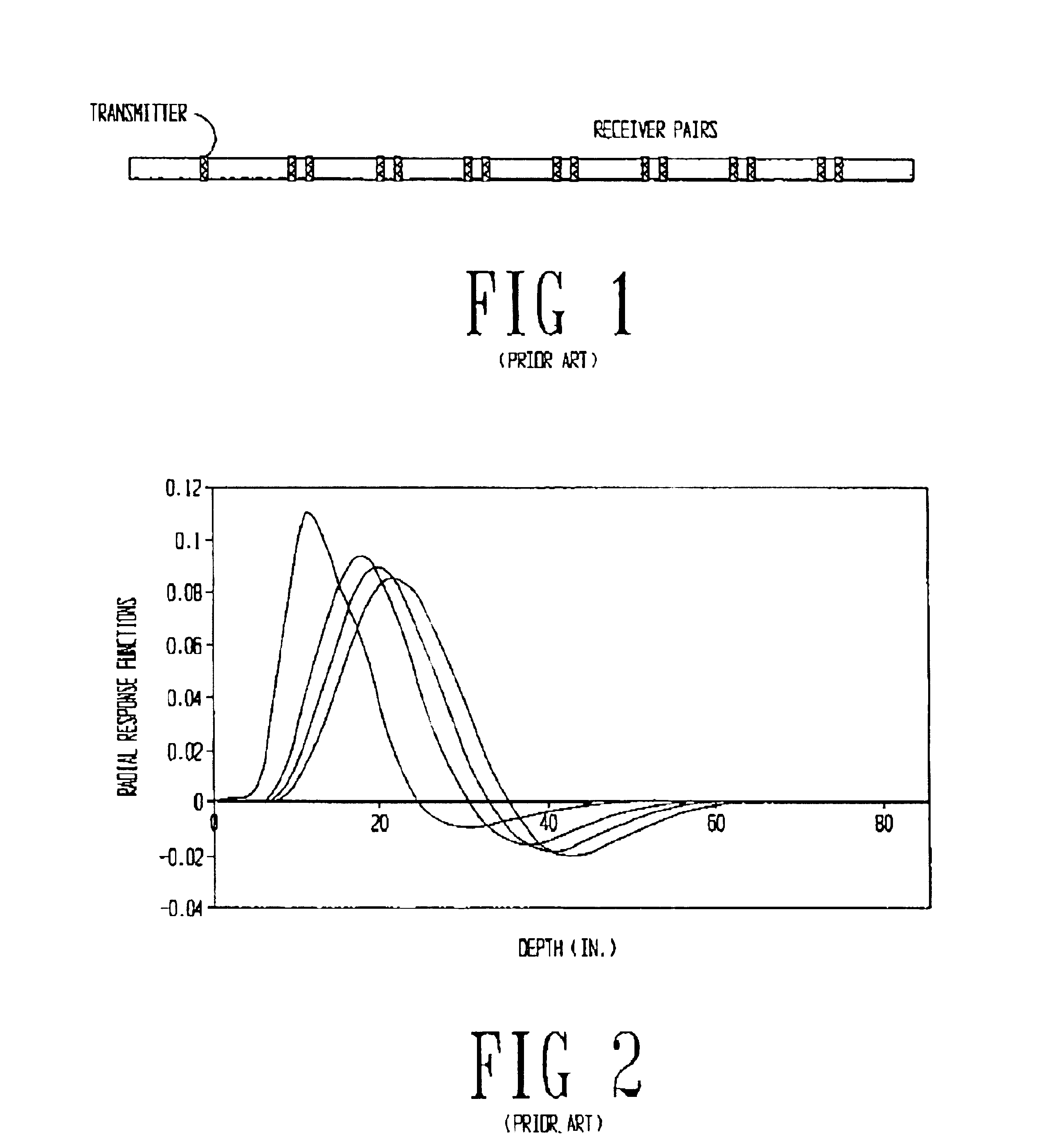
However, the inventors of the present specification have found that the radial response function calculation of the prior art is only valid when assuming small resistivity differences in the annulus.
Therefore, the fixed depth of investigation curves based on these functions are prone to error.

Method used


Image

  • Fixed-depth of investigation log for multi-spacing multi-frequency LWD resistivity tools
  • Fixed-depth of investigation log for multi-spacing multi-frequency LWD resistivity tools
  • Fixed-depth of investigation log for multi-spacing multi-frequency LWD resistivity tools

Examples


Embodiment Construction

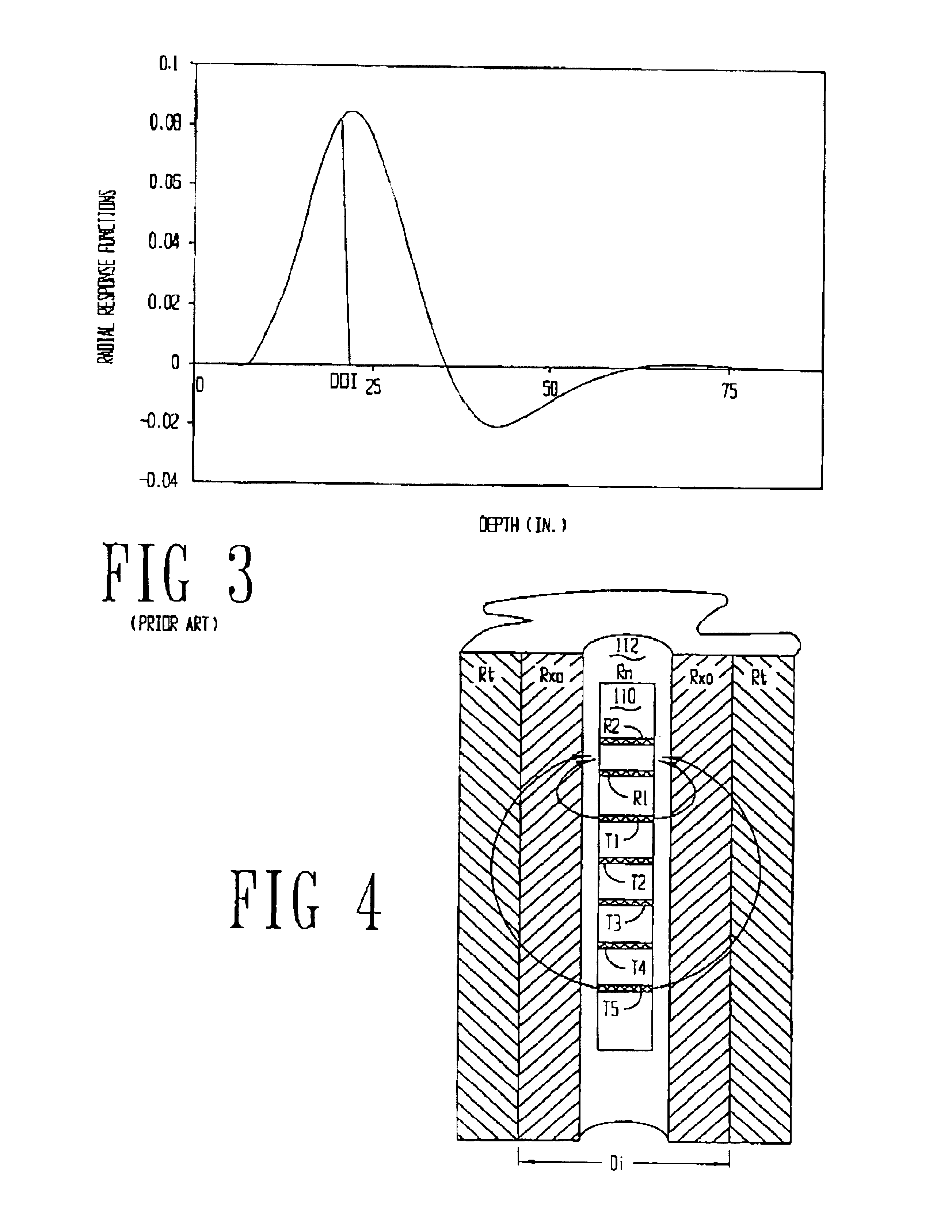
The problems noted above are solved in large part by a logging while drilling (LWD) tool that operates under the realization that the depth of investigation in high frequency electromagnetic resistivity tools is affected not only by the frequency of the electromagnetic wave used and the transmitter-to-receiver spacings, but also by the resistivity of the formation, and the resistivity contrast between the invaded zone and formation. More particularly, the specification discloses an electromagnetic resistivity LWD tool preferably having five transmitting antennas spaced apart from each other and from a set of two receiving antennas. Each of the transmitters operates at three distinct frequencies: 2 megahertz, 500 kilohertz, and 250 kilohertz. Thus, the preferred embodiments of the present invention are capable of measuring resistivity of a formation at several different frequencies, and at several different depths of investigation based in part on the transmitter-to-receiver spacing....


PUM


Abstract

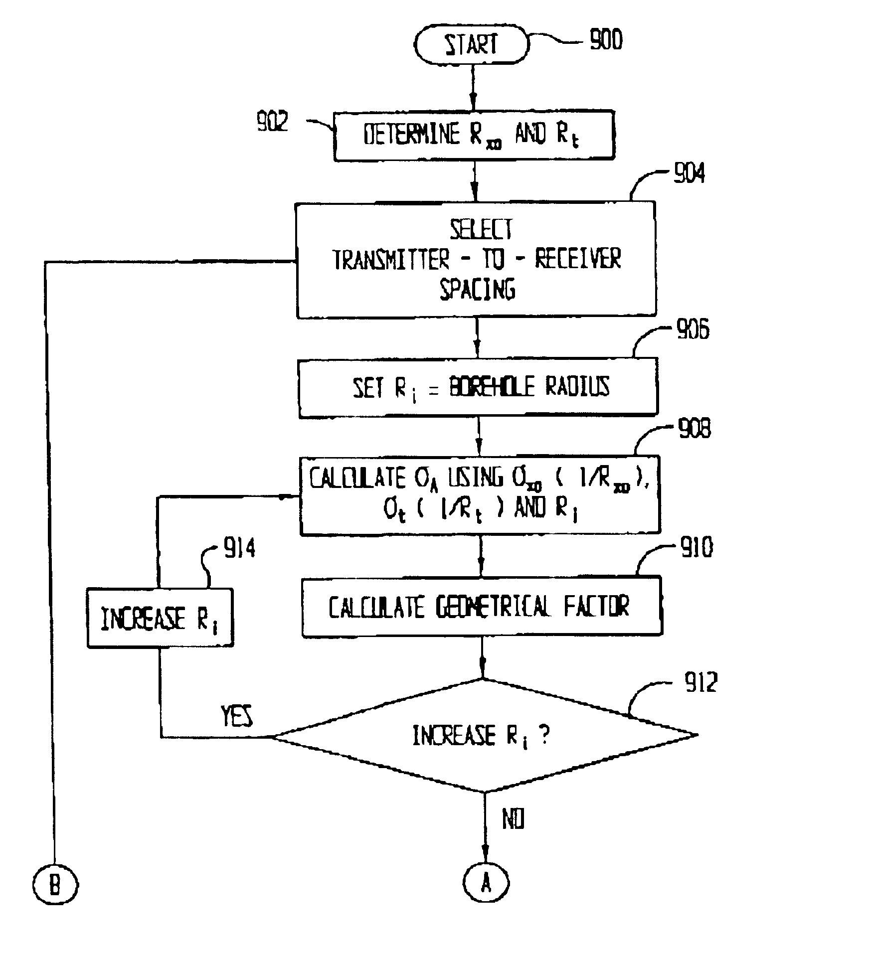
A system and related method for obtaining electromagnetic resistivity logs of a formation having fixed depths of investigation that differ from the actual depths of investigation for the tool. The system and related method comprises calculating actual invaded zone and formation resistivities, and then using least-squares curve fitting techniques to find a function that models the relationship between the physical spacing of the transmitters and the depths of investigation. Using the function, it is possible to find a transmitter-to-receive spacing that, though not actually wed, would give the desired depth of investigation. This transmitter-to-receiver spacing is then used in combination with a second function, determined using least-squares curve fitting methods, which models the relationship between the transmitter-to-receiver physical spacing and the measured resistivity to obtain the resistivity reading at a fixed depth of investigation.

Description

None.Not applicable.1. Field of the InventionThe preferred embodiments of the present invention are directed generally to downhole logging tools and logs created with the tools. More particular, the preferred embodiments are directed to logging-while-drilling (LWD) resistivity tools and logs created with the resistivity tools. More particularly still, the preferred embodiments of the present invention are directed to determining fixed depths of investigation for LWD tools having multiple spaced transmitters and receivers and using multiple frequencies.2. Background of the InventionIn the days before logging-while-drilling (LWD) tools, information regarding downhole formations was gathered using wireline logging tools. One such wireline logging tool is a resistivity tool for determining resistivity of the downhole formation. Resistivity is generally determined at several depths of investigation, where the depths of investigation in a conventional wireline tool operating at a low freq...

Claims


Application Information

Patent Timeline
Patent Type & Authority Patents(United States)
IPC IPC(8): G01V3/28G01V3/18
CPCG01V3/28G01V3/30
Inventor BITTAR, MICHAEL S.HU, GUOYU
Owner HALLIBURTON ENERGY SERVICES INC
Learn More