Microfluidic system (EDI)

a microfluidic system and microfluidic technology, applied in the direction of fluid speed measurement, optical light guide, microreactor, etc., can solve the problems of imposing extra complexity on the design and use, affecting the production cost, and easiness of handling, so as to improve the efficiency and improve the presentation of ms-sample/ms-analyte, the effect of minimising the loss of precious materials

Inactive Publication Date: 2004-11-02
GYROS
View PDF34 Cites 106 Cited by
  • Summary
  • Abstract
  • Description
  • Claims
  • Application Information

AI Technical Summary

Benefits of technology

A second object is to provide improved microfluidic methods and means for sample handling before presentation of a sample analyte as an MS-analyte. Sub-objects are to provide an efficient concentration, purification and / or transformation of a sample within the microfluidic device while maintaining a reproducible yield / recovery, and / or minimal loss of precious material.
A third object is to provide improved microfluidic methods and means that will enable efficient and improved presentation of an MS-sample / MS-analyte. This object applies to MS-samples that are presented on an EDI-surface.
A sixth object is to provide a cheap and disposable microfluidic device unit enabling parallel sample treatments and having one or more MS-ports that are adapted to a mass spectrometer that require energy desorption / ionisation of an MS-analyte from a surface by input of energy.

Problems solved by technology

These means are electrical connections, pumps etc, which impose an extra complexity on the design and use and may negatively influence the production costs, easiness of handling etc.

Method used


Image

  • Microfluidic system (EDI)
  • Microfluidic system (EDI)
  • Microfluidic system (EDI)

Examples


example 1

Gold at Different Positions in a CD

This table shows the results form a summary of experiments performed before the priority date in order to optimise the design of the CD-MALDI interface. Gold was sputtered at various positions of the CD and the MALDI characteristics were studied for a tryptic digest of Bovine Serum Albumin (BSA). The CD was placed on a metal adapter inserted into the ion source. The gold was hence patterned in various ways to determine the importance of electrical contact between the MALDI ports and the adapter plate.

example 2

Planar CD and Structured Removable Lid

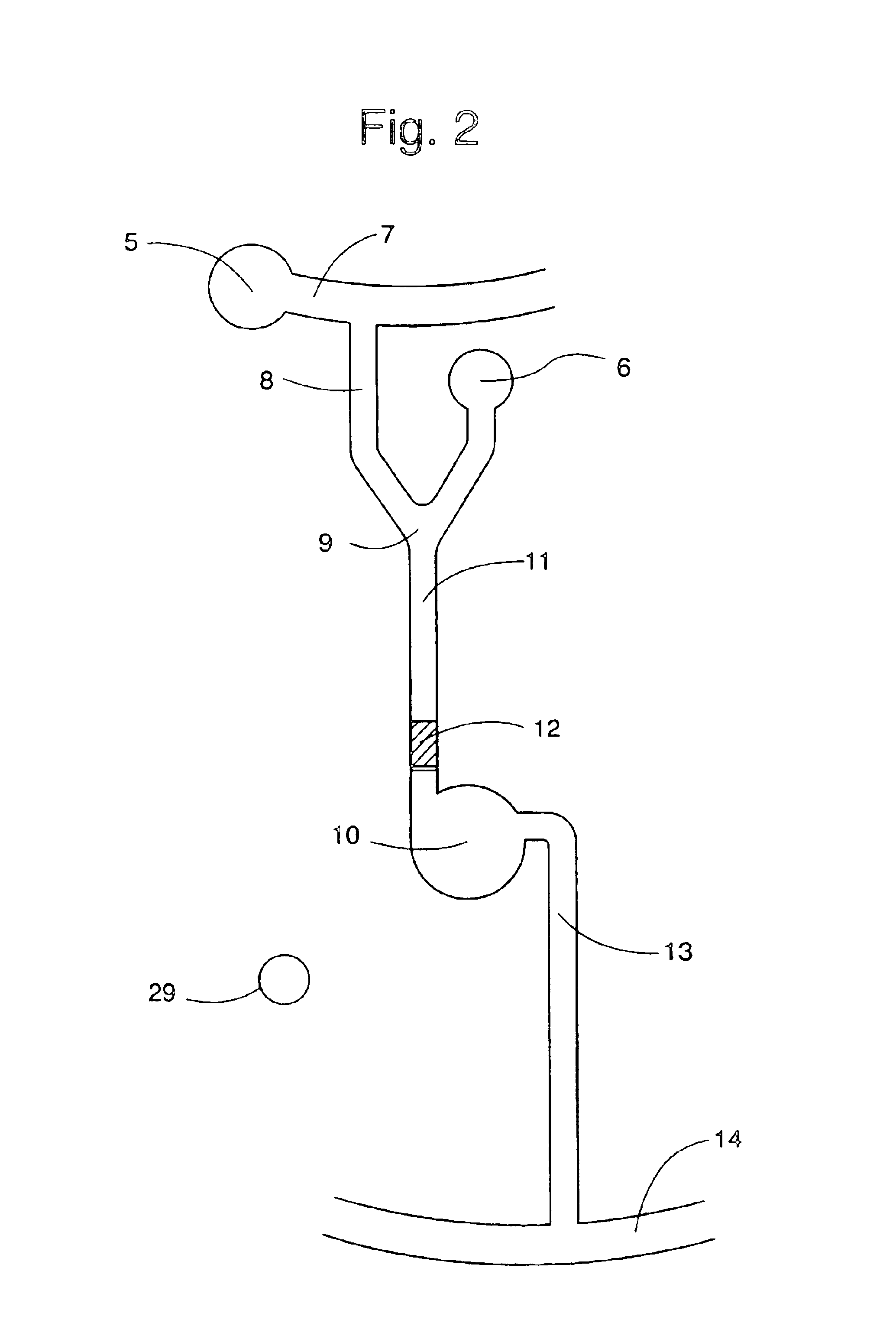
This example shows a planar CD in combination with a lid in which the microfluidic structures are present. The structured lid was achieved through casting Memosil (Hereaus, Germany) against a nickel-coated master. The microfluidic structure employed in this example is shown in FIG. 2.

The structured lid is attached to the CD by adhesion forces. The surface facing the lid should be hydrophilic as the presented invention utilizes capillary action to fill the microfluidic structures. This is especially important as the moulded lid, being a type of silicon rubber is hydrophobic.

The upper side of the CD was covered with gold using a DC Bias magnetron sputtering method (1* 10-5 torr, Ar plasma and titan as adhesion layer) and made hydrophilic according to the following procedure; The gold sputtered side was cleaned by rinsing with ethanol, followed by an oxygen plasma treatment (Plasma Science PSO500,). After plasma cleaning a self-assembled monolayer ...

example 3

Structured CD and Site-specific Elution

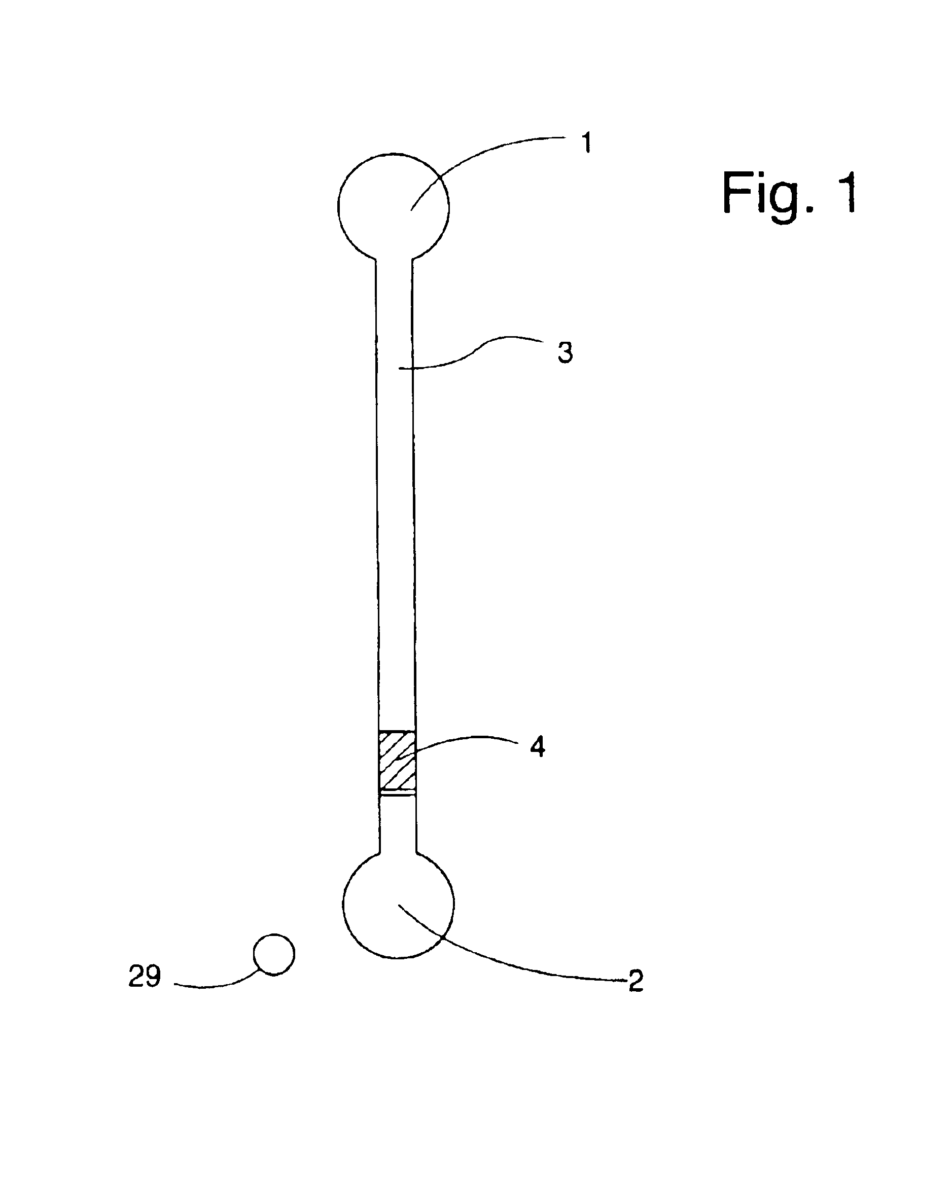
This example employs a CD with integrated microfluidic structures, a thin (.ltoreq.70 .mu.m) lid with holes at positions matching the MALDI port in the CD. The microfluidic structure employed in this example is shown in FIG. 1.

The polycarbonate CD was covered with gold as described above. The side was hydrophilized using the thiolprocedure described above. The lid (SkultunaFlexible, Skultuna, Sweden), having, pre-drilled holes, was attached to the CD through heat pressing at 135.degree. C.

Reversed phase beads (Source 15 RPC) with a diameter of 15 .mu.m were packed in the individual structures using capillary forces in combination with centrifugation. The columns were rinsed with ethanol and spun to dryness before 23 fmol of tryptically digested BSA was added and spun down using 700 rpm. The tryptic digest of BSA was generated according to the procedure described above. After sample addition, the column was rinsed twice with water. .alpha.-cyano...


PUM

PropertyMeasurementUnit
widthaaaaaaaaaa
widthaaaaaaaaaa
distanceaaaaaaaaaa

Abstract

A microfluidic device in form of a disc comprising an MS-port for presentation of an MS-analyte to an EDI-MS apparatus, said MS-port is a part of a microchannel structure (I) comprising an inlet port for a sample, and comprises an EDI-area having a conductive layer (I) and an EDI-surface from which the MS-analyte is to be desorbed / ionised. The device is characterized in that layer (I) has a conductive connection and / or that there is a calibrator area in the proximity of each of said one, two or more MS-ports. In a typical variant the MS-port is in the form of a depression that is in fluid communication with upstream part of microchannel structure (I).

Description

The present invention relates to a microfluidic device, which can be interfaced to a mass spectrometer (MS). The device comprises a microchannel structure, which has a first port (inlet port) and a second port (outlet port). A sample to be analysed is applied to the first port and presented to the mass spectrometer in the second port. This second port will be called an MS-port. There may be additional inlet and outlet ports, and also additional identical or similar microchannnel structures. During passage through the microchannel structure the sample is prepared to make it suitable for analysis by mass spectrometry.The sample presented in an MS-port will be called an MS-sample. An analyte in an MS-sample is an MS-analyte. "Sample" and "analyte" without prefix will primarily refer to a sample applied to an inlet port.Conductive and non-conductive properties are with respect to conducting electricity.The present invention concerns mass spectrometry in which the MS-samples are subjecte...

Claims


Application Information

Patent Timeline
Patent Type & Authority Patents(United States)
IPC IPC(8): B01L3/00B01F13/00B01F5/06B01J19/00G01N33/543G01N35/00H01J49/04H01J49/02B01F15/02G01N27/62B81B1/00B81B7/04G01N27/64G01N31/20G01N35/08G01N37/00H01J49/10
CPCB01F5/0646H01J49/0431B01F5/0655B01F13/0059B01F15/0233B01J19/0093B01L3/5025B01L3/502715G01N33/54366G01N35/00069H01J49/0418B01F5/0647B01F15/0201B01L2200/027B01L2200/0605B01L2200/10B01L2200/142B01L2300/069B01L2300/0803B01L2300/0806B01L2300/0861B01L2300/0864B01L2300/0867B01L2300/087B01L2300/16B01L2400/0406B01L2400/0409B01L2400/0418B01L2400/0633B01L2400/0688G01N2035/00504B01F25/4338B01F25/4331B01F25/433B01F33/30B01F35/71B01F35/71725
Inventor ANDERSSON, PERGUSTAFSSON, MAGNUSPALM, ANDERSWALLENBORG, SUSANNEHELLERMARK, CECILIA
Owner GYROS
Why Eureka
Try Eureka