Microfludic system (EDI)

a microfludic system and fluorescence technology, applied in the direction of positive displacement liquid engine, isotope separation, particle separator tube, etc., can solve the problems of imposing extra complexity on the design and use, negatively affecting production costs, easiness of handling etc., and achieve efficient and improved presentation of ms-sample/ms-analyte, the effect of minimising the loss of precious materials

Inactive Publication Date: 2004-04-06
GYROS
View PDF41 Cites 205 Cited by
  • Summary
  • Abstract
  • Description
  • Claims
  • Application Information

AI Technical Summary

Benefits of technology

A second object is to provide improved microfluidic methods and means for sample handling before presentation of a sample analyte as an MS-analyte. Sub-objects are to provide an efficient concentration, purification and / or transformation of a sample within the microfluidic device while maintaining a reproducible yield / recovery, and / or minimal loss of precious material.
A third object is to provide improved microfluidic methods and means that will enable efficient and improved presentation of the MS-sample / MS-analyte. This object in particular applies to MS-samples that are presented on a surface, i.e. an EDI surface.
A sixth object is to provide a cheap and disposable microfluidic device unit enabling parallel sample treatments and having one or more MS-ports that are adapted to a mass spectrometer.
A fourth subaspect is similar to the third subaspect in the sense that there is a lid covering at least a part of each microchannel structures. In this subaspect the lid also covers or restricts the openings of the MS-ports and is removable to an extent that enables exposure of the opening in each MS-port, for instance exposing the surfaces of EDI areas. For EDI ports the removal will facilitate irradiation and the desorption / ionisation of the MS-analyte. The removal may also facilitate evaporation of volatile components.

Problems solved by technology

This kind of transporting means imposes an extra complexity on the design and use, which in turn may negatively influence the production costs, easiness of handling etc of these devices.

Method used


Image

  • Microfludic system (EDI)
  • Microfludic system (EDI)
  • Microfludic system (EDI)

Examples


example 1

Gold at Different Positions in a CD

This table shows the results form a summary of experiments performed in order to optimise the design of the CD-MALDI interface. Gold was sputtered at various positions of the CD and the MALDI characteristics were studied for a tryptic digest of Bovine Serum Albumin (BSA). The CD was placed on a metal adapter inserted into the ion source. The gold was hence patterned in various ways to determine the importance of electrical contact between the MALDI ports and the adapter plate.

example 2

Testing of Crystallization on the MALDI Surface

Microfluidic device: The CD was fabricated of polycarbonate. Each microchannel structure in the CD only contained an inlet port (uppstreams), the ms-port (downstreams) and a flow conduit between. The inlet and ms-port consisted of open areas made by drilling holes in the lid before covering the CD with the lid, i.e., the open areas on the CD was in contact with the surrounding atmosphere. Only a minor part of the flow conduit at the ms-port was in connection to the open area. The width and the depth of the microchannel leading into the ms-port were 100 .mu.m and 40 .mu.m, respectively. The open area of the ms-port had a cylindrical geometry with a diameter of 300 .mu.m (drilled hole) and depth 70 .mu.m., where the depth is the thickness of the lid. The bottom of the open area, therefore, constituted of the upper surface of the CD (and a minor part of the microfluidic channel) while the walls surrounding the open area, and restricting th...

example 3

Planar CD and Structured Removable Lid

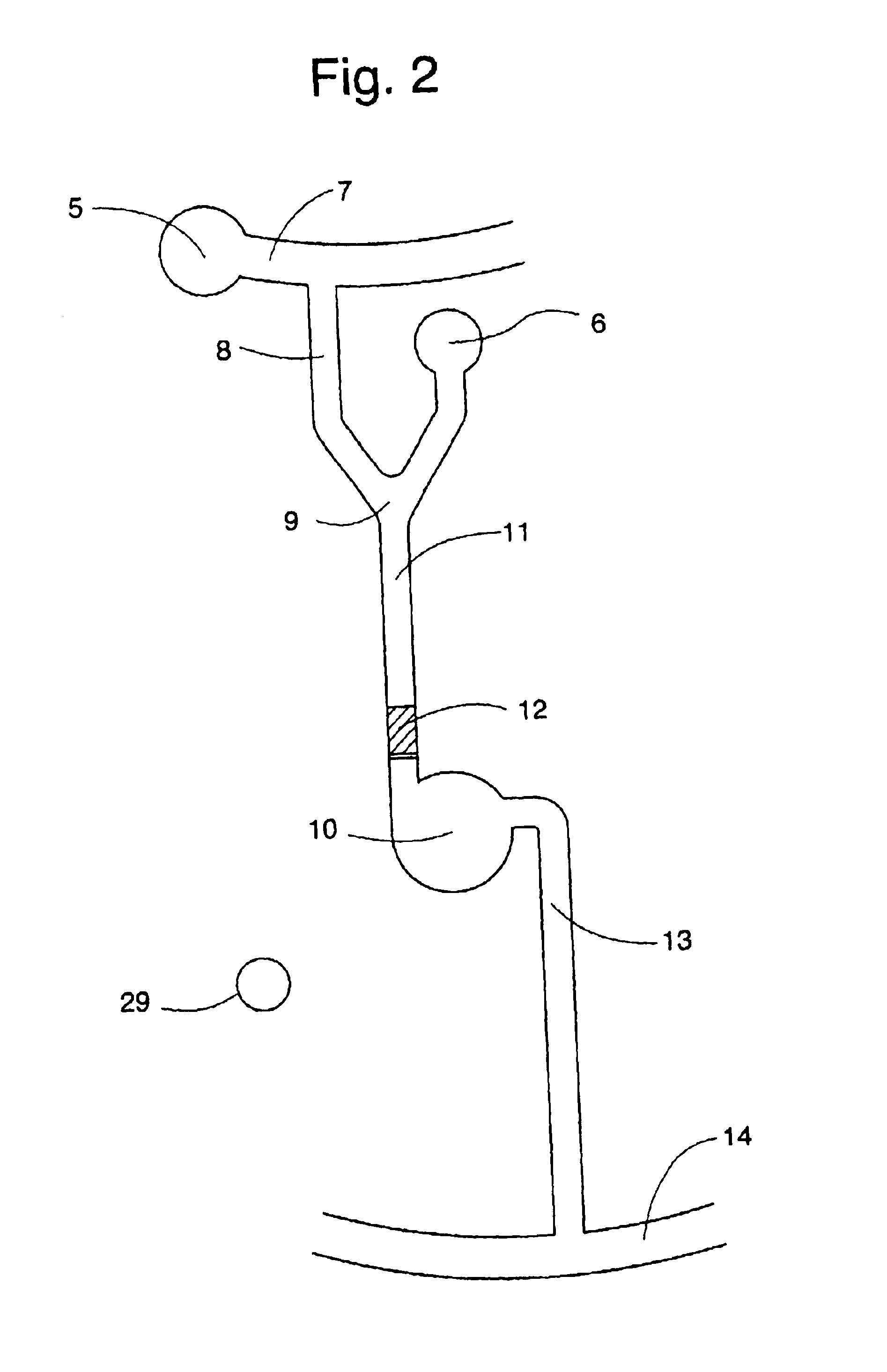
This example shows a planar CD in combination with a lid in which the microfluidic structures are present. The structured lid was achieved through casting Memosil (Hereaus, Germany) against a nickel-coated master. The microfluidic structure employed in this example is shown in FIG. 2.

The structured lid is attached to the CD by adhesion forces. The surface facing the lid should be hydrophilic as the presented invention utilizes capillary action to fill the microfluidic structures. This is especially important as the moulded lid, being a type of silicon rubber is hydrophobic.

The upper side of the CD was covered with gold using a DC Bias magnetron sputtering method (1* 10-5 tort, Ar plasma and titan as adhesion layer) and made hydrophilic according to the following procedure; The gold sputtered side was cleaned by rinsing with ethanol, followed by an oxygen plasma treatment (Plasma Science PSO500,). After plasma cleaning a self-assembled monolayer ...


PUM

PropertyMeasurementUnit
widthaaaaaaaaaa
widthaaaaaaaaaa
distanceaaaaaaaaaa

Abstract

A microfluidic device comprising an MS-analyte presentation unit for a EDI-MS apparatus, said unit comprising an essentially planar support plate which on one side has one, two or more ports (MS-ports) comprising an area (EDI area) for presenting the MS-analyte to a mass spectrometer. The EDI area comprises a layer I of conducting material. The characteristic feature of the device is that layer (I) has a conductive connection and / or that there is a calibrator area in the proximity of the MS-port.

Description

The present invention relates to a microfluidic device, which can be interfaced to a mass spectrometer (MS). The device comprises a microchannel structure having a first port (inlet port) and a second port (outlet port). A sample to be analysed is applied to the first port and presented to the mass spectrometer in the second port. This second port will be called an MS-port. There may be additional inlet and outlet ports. During passage through the microchannel structure the sample is prepared to make it suitable for analysis by mass spectrometry.The sample presented in an MS-port will be called an MS-sample. An analyte in an MS-sample is an MS-analyte. "Sample" and "analyte" without prefix will primarily refer to a sample applied to an inlet port.One important aspect of the present invention concerns mass spectrometry in which the MS-samples are subjected to Energy Desorption / Ionisation from a surface by input of energy. Generically this kind of process will be called EDI and the su...

Claims


Application Information

Patent Timeline
Patent Type & Authority Patents(United States)
IPC IPC(8): B01L3/00B01J19/00G01N33/543G01N35/00H01J49/04H01J49/02
CPCB01J19/0093B01L3/5027B82Y30/00G01N33/54366G01N35/00069H01J49/04B01L3/5025Y10T436/25375B01L3/502715B01L3/50273B01L2200/0605B01L2200/10B01L2300/069B01L2300/0803B01L2300/0806B01L2300/0861B01L2300/0864B01L2300/0867B01L2300/087B01L2400/0406B01L2400/0409B01L2400/0688G01N2035/00504Y10T436/25Y10T436/24
Inventor ANDERSSON, PERDERAND, HELENEGUSTAFSSON, MAGNUSPALM, ANDERSWALLENBORG, SUSSANNE
Owner GYROS
Why Eureka
Try Eureka