Microfluidic devices and methods

a technology applied in the field of microfluidic devices and methods, can solve the problems of imposing an extra complexity on the design and use, negatively affecting production costs, and easiness of handling etc. of these devices

Inactive Publication Date: 2003-04-10
GYROS
View PDF4 Cites 46 Cited by
  • Summary
  • Abstract
  • Description
  • Claims
  • Application Information

AI Technical Summary

Benefits of technology

0031] A first object is to provide improved means and methods for transporting samples, analytes including fragments and derivatives, reagents etc in microfluidic devices that are capable of being interfaced with a mass spectrometer.

Problems solved by technology

These kinds of transporting means impose an extra complexity on the design and use, which in turn may negatively influence the production costs, easiness of handling etc of these devices.

Method used


Image

  • Microfluidic devices and methods
  • Microfluidic devices and methods
  • Microfluidic devices and methods

Examples


example 2

Planar CD and Structured Removable Lid

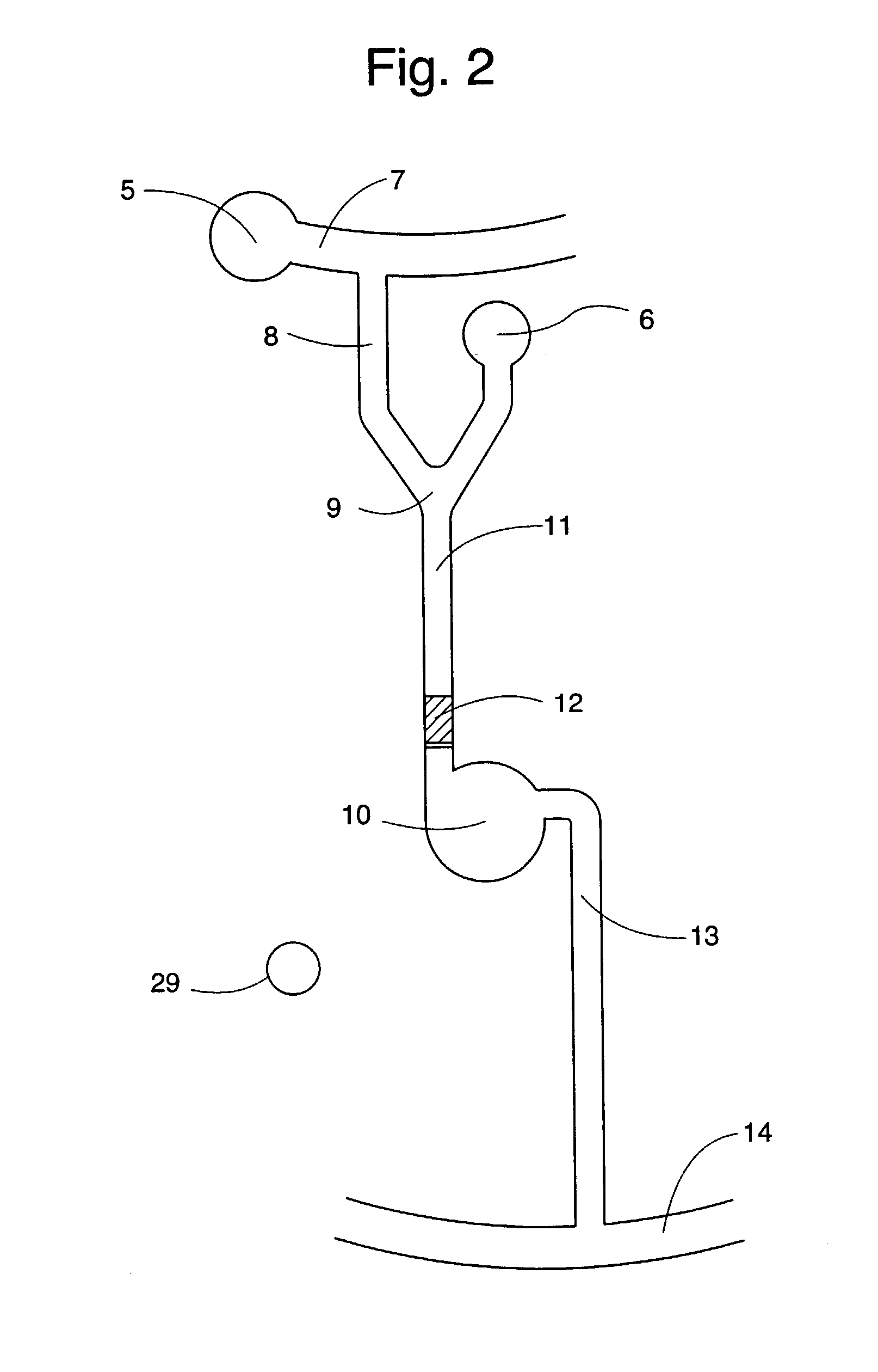
[0185] This example shows a planar CD in combination with a lid in which the microfluidic structures are present. The structured lid was achieved through casting Memosil (Hereaus, Germany) against a nickel-coated master. The microfluidic structure employed in this example is shown in FIG. 2.

[0186] The structured lid is attached to the CD by adhesion forces. The surface facing the lid should be hydrophilic as the presented invention utilizes capillary action to fill the microfluidic structures. This is especially important as the moulded lid, being a type of silicon rubber is hydrophobic.

[0187] The upper side of the CD was covered with gold using a DC Bias magnetron sputtering method (1*10-5 torr, Ar plasma and titan as adhesion layer) and made hydrophilic according to the following procedure; The gold sputtered side was cleaned by rinsing with ethanol, followed by an oxygen plasma treatment (Plasma Science PSO500,). After plasma cleaning a self-...

example 3

Structured CD and Site-Specific Elution

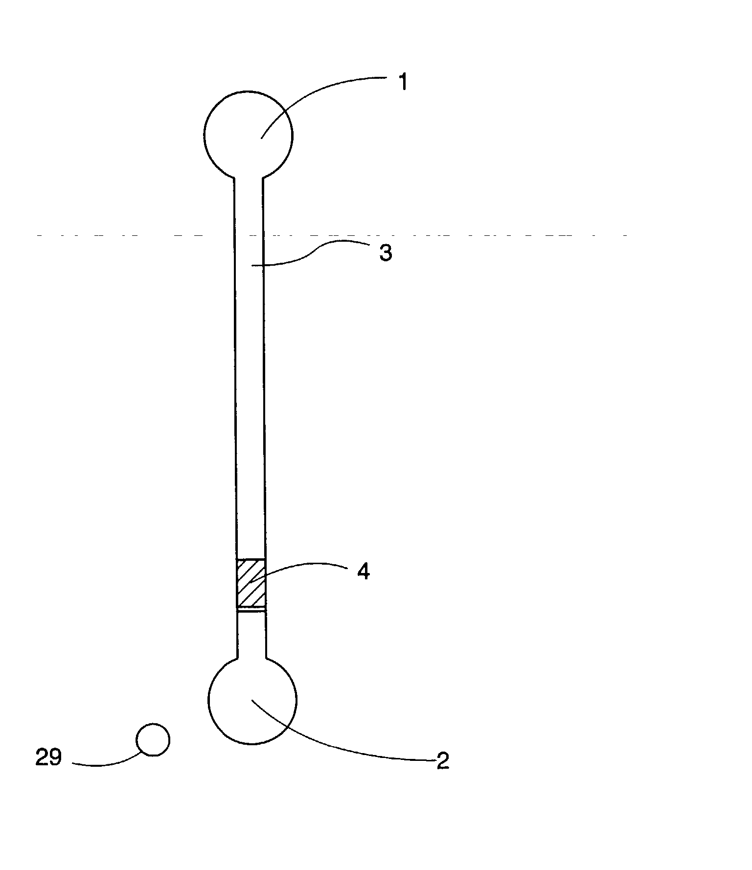
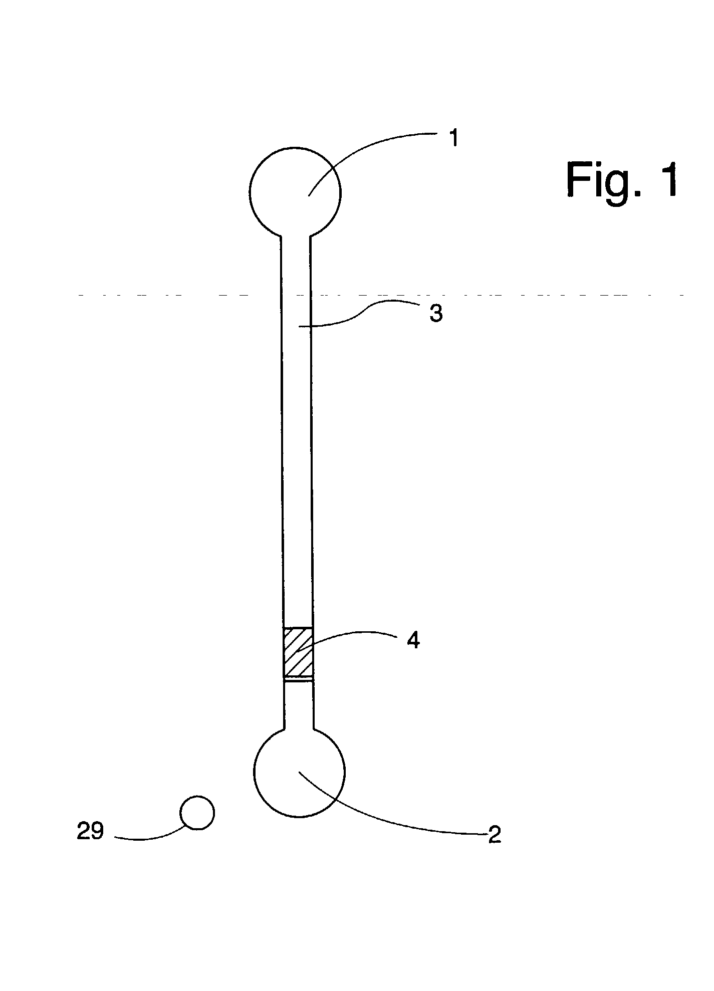
[0193] This example employs a CD with integrated microfluidic structures, a thin (.ltoreq.70 .mu.m) lid with holes at positions matching the MALDI port in the CD. The microfluidic structure employed in this example is shown in FIG. 1.

[0194] The polycarbonate CD was covered with gold as described above. The side was hydrophilized using the thiolprocedure described above. The lid (SkultunaFlexible, Skultuna, Sweden), having, pre-drilled holes, was attached to the CD through heat pressing at 135.degree. C.

[0195] Reversed phase beads (Source 15 RPC) with a diameter of 15 .mu.m were packed in the individual structures using capillary forces in combination with centrifugation. The columns were rinsed with ethanol and spun to dryness before 23 fmol of tryptically digested BSA was added and spun down using 700 rpm. The tryptic digest of BSA was generated according to the procedure described above. After sample addition, the column was rinsed twice with...

example 4

Parallel Sample Preparation in a Product CD

[0197] Description of the Microfluidic Disc (CD)

[0198] FIG. 8a illustrate a product microfluidic device (CD) (1000) comprising 10 sets (1001) of identical microchannel structures (1002) arranged annularly around the spinning axis (axis of symmetry) (1003) of a circular disc (1000). Each set comprises 10 microchannel structures. Each microchannel structure is oriented radially with an inlet port (1004,1005) located at shorter radial distance than an outlet port (MS-port) (1006). The MS-ports are 0.9 cm from the edge of the disc (not shown). The disc was of the same size as a conventional CD. The CD has a home mark (1035) at the edge (1036) for positioning the disc when dispensing liquids.

[0199] The final device comprises a bottom part in plastic material that contains the uncovered form of the microchannel structures given in FIG. 8a. The microchannel structures are covered with a lid in which there are circular holes (1007,1008,1009,1010,10...


PUM

PropertyMeasurementUnit
widthaaaaaaaaaa
widthaaaaaaaaaa
distanceaaaaaaaaaa

Abstract

A method for presenting an analyte of a liquid sample as an MS-analyte to a mass spectrometer. The method is characterized in (a) comprising the steps of: (i) applying the liquid sample to a sample inlet port (I) of a microchannel structure (I) of a microfluidic device, said structure also comprising an MS-port, (ii) transporting the analyte by a liquid flow in microchannel structure (I) thereby transforming the analyte to an MS-analyte, and (iii) presenting the MS-analyte to a mass spectrometer via the MS-port, and (b) using inertia force for creating said liquid flow within at least a part of microchannel structure (I). A microfluidic disc comprising (a) an axis of symmetry perpendicular to the plane of the disc, (b) a microchannel structure (I) comprising an inner application area at a shorter radial distance than an outlet port, and an MS-port and a sample inlet port (I).

Description

[0001] The present invention relates to a microfluidic device, which can be interfaced to a mass spectrometer (MS). The device comprises a microchannel structure having a first port (inlet port) and a second port (outlet port). A sample to be analysed is applied to the first port and presented to the mass spectrometer in the second port. This second port will be called an MS-port. There may be additional inlet and outlet ports. During passage through the microchannel structure the sample is prepared to make it suitable for analysis by mass spectrometry.[0002] The sample presented in an MS-port will be called an MS-sample. An analyte in an MS-sample is an MS-analyte. "Sample" and "analyte" without prefix will primarily refer to a sample applied to an inlet port.[0003] Conductive and non-conductive properties are with respect to conducting electricity.[0004] The invention concerns mass spectrometry in which the MS-samples are subjected to Energy Desorption / Ionisation from a surface by...

Claims


Application Information

Patent Timeline
Patent Type & Authority Applications(United States)
IPC IPC(8): B01J19/00B01L3/00G01N33/543G01N35/00
CPCB01J19/0093G01N2035/00504B01L3/502753B01L2200/0605B01L2200/10B01L2300/069B01L2300/0803B01L2300/0806B01L2300/0861B01L2300/0864B01L2300/0867B01L2300/087B01L2400/0406B01L2400/0409B01L2400/0688B82Y30/00G01N33/54366G01N35/00069B01L3/5025
Inventor ANDERSSON, PERDERAND, HELENEGUSTAFSSON, MAGNUSPALM, ANDERSWALLENBORG, SUSSANNEHELLERMARK, CECILIA
Owner GYROS
Why Eureka
Try Eureka