Milker unit detacher for rotary milking parlor

a technology of milker unit and milking parlor, which is applied in the direction of milking devices, catheters, animal husbandry, etc., can solve the problems of increasing the fatigue and turnover of dairy operators, and the insufficient prior art detachable system

Inactive Publication Date: 2004-11-09
GEA FARM TECH
View PDF42 Cites 31 Cited by
  • Summary
  • Abstract
  • Description
  • Claims
  • Application Information

AI Technical Summary

Benefits of technology

A rotating platform 102 can include any number of stalls, and typically includes from 16 to 100 stalls. In the illustrated embodiment, the rotating platform is about 40 inches (1016 mm) above the floor 116. The rotating platform 102 slopes away from the operator, which in the illustrated embodiment, is toward the center. Such a slope eliminates run-off into an operator area 123.

Problems solved by technology

This prior art detacher system is inadequate for a number of reasons.
In a high throughput operation like a rotary milking parlor, this extra movement required to attach the milker unit contributes significant dairy operator fatigue and turnover.

Method used


Image

  • Milker unit detacher for rotary milking parlor
  • Milker unit detacher for rotary milking parlor
  • Milker unit detacher for rotary milking parlor

Examples


Embodiment Construction

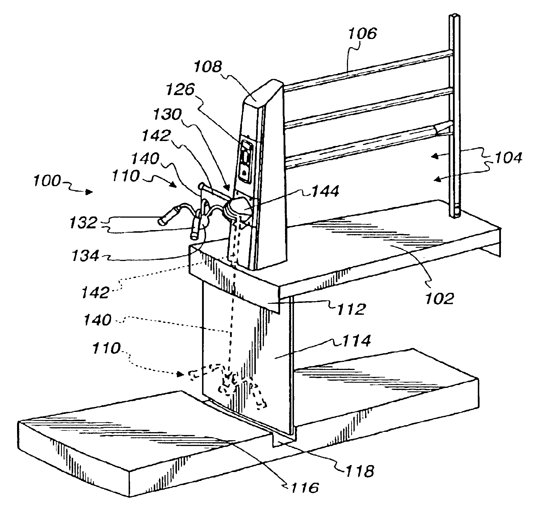
Illustrated generally in FIGS. 5 through 13 is a rotary milking parlor 100 in accordance with the present invention. The rotary milking parlor 100 includes a rotating platform 102 having a number of cow stalls 104 defined by side rails 106, front rails 107, and end posts 108.

As seen in FIGS. 6 through 13, the rotating platform 102 is elevated so that an operator (not pictured) can prepare cows for milking and attach milker units 110 without bending over. The rotating platform 102 includes a rim plate 112 and an apron 114. Beneath the rotating platform 102 is a floor 116 with a recess 118 in which the apron 114 is disposed for rotation to prevent access to the underside of the rotating platform 102. The illustrated rotary milking parlor 100 is an "external" system in which operators stand outside the perimeter of the rotating platform 102. The present invention will also work with an "internal" system, in which the rotating platform has a central opening in which an operator can stan...


PUM


Abstract

A rotary milking parlor milker detacher having a pivoting support arm and retracting chain arrangement that is synchronized with a rotating platform position to move the detacher between a storage position, a presentation position, and a milking position to protect the detacher from damage and provide a superior ergonomic design that reduces operator fatigue and turnover.

Description

FIELD AND BACKGROUND OF THE INVENTIONThis invention relates generally to rotary milking parlors and more particularly to milker unit detachers for use in rotary milking parlors.Rotary milking parlors include a rotating platform having a number of stalls in which cows are milked as the platform rotates. The platform must rotate constantly to be efficient, so the speed of rotation must be slow enough to permit cows to step safely from a stationary platform to the rotating platform.The benefit of such an arrangement is that dairy operators are able to stand in a single location to prepare cows for milking and attach milker units to the cows. This reduces operator fatigue and improves throughput efficiency. Nonetheless, throughput in a rotary milking parlor is increased to a level at which operator fatigue and turnover remain significant issues.One complication of such a system is the placement and storage of milker units. In stationary stall dairies, milker units can be placed at the r...

Claims


Application Information

Patent Timeline
Patent Type & Authority Patents(United States)
IPC IPC(8): A01J5/017A01J5/00A01K1/12A01K1/00
CPCA01K1/123A01J5/017
Inventor HEIN, PATRICK M.HANSON, JEFFREY S.HEINRICH, MICHAELHOELSCHER, FRANKLARSON, LARRY G.KAEVER, PETERSCHONROCK, KARSTEN
Owner GEA FARM TECH
Why Eureka
Try Eureka