Inertia clutch mechanism in motors to prevent backdrive

a technology of clutch mechanism and motor, which is applied in the direction of gearing details, wing accessories, gearing, etc., can solve the problems of reducing the overall system efficiency, increasing the cost of the system, and reducing the gearing efficiency

Inactive Publication Date: 2004-11-09
RPX CORP +1
View PDF26 Cites 28 Cited by
  • Summary
  • Abstract
  • Description
  • Claims
  • Application Information

AI Technical Summary

Benefits of technology

Other objects, features and characteristics of the present invention, as well as the methods of operation and the functions of the related elements of the structure, the combination of parts and economics of manufacture will become more apparent upon consideration of the following detailed description and appended claims with reference to the accompanying drawings, all of which form a part of this specification.

Problems solved by technology

Currently this function is achieved by decreasing the gearing efficiency; however, the negative effect is that the overall system efficiency is decreased as well, possibly requiring a larger motor.
These configurations are comprised of numerous small components that add cost to the system.

Method used


Image

  • Inertia clutch mechanism in motors to prevent backdrive
  • Inertia clutch mechanism in motors to prevent backdrive
  • Inertia clutch mechanism in motors to prevent backdrive

Examples


Embodiment Construction

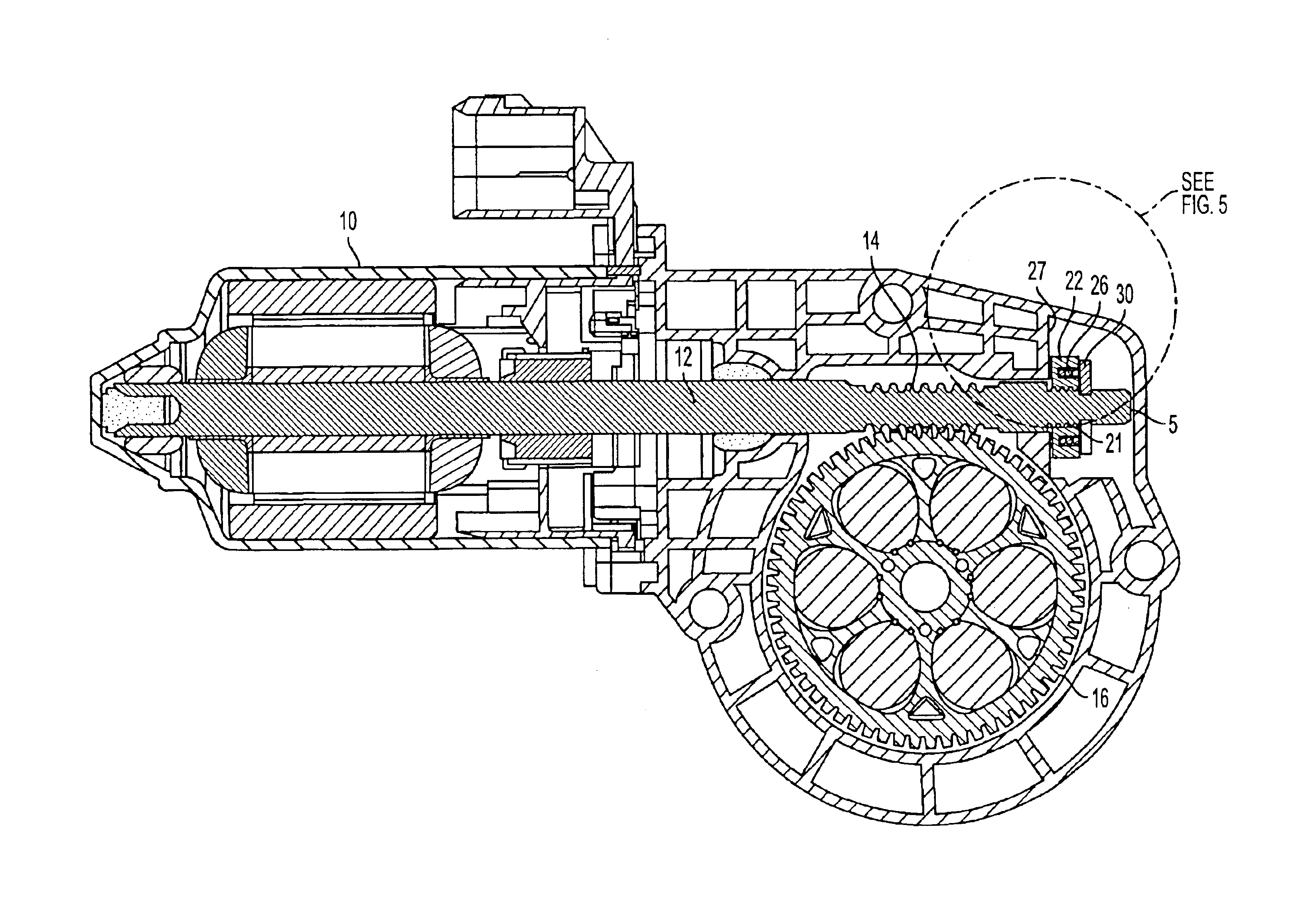
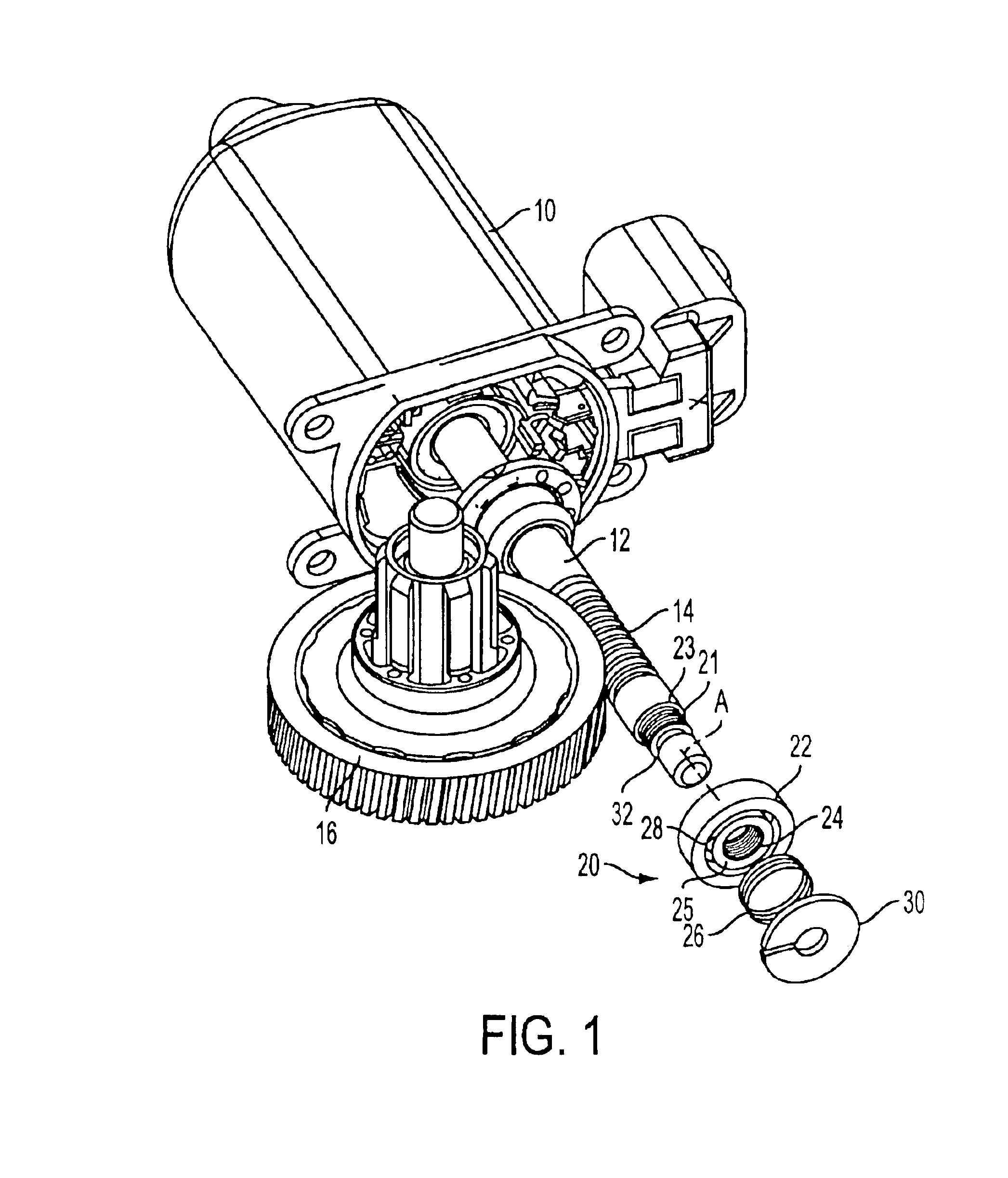
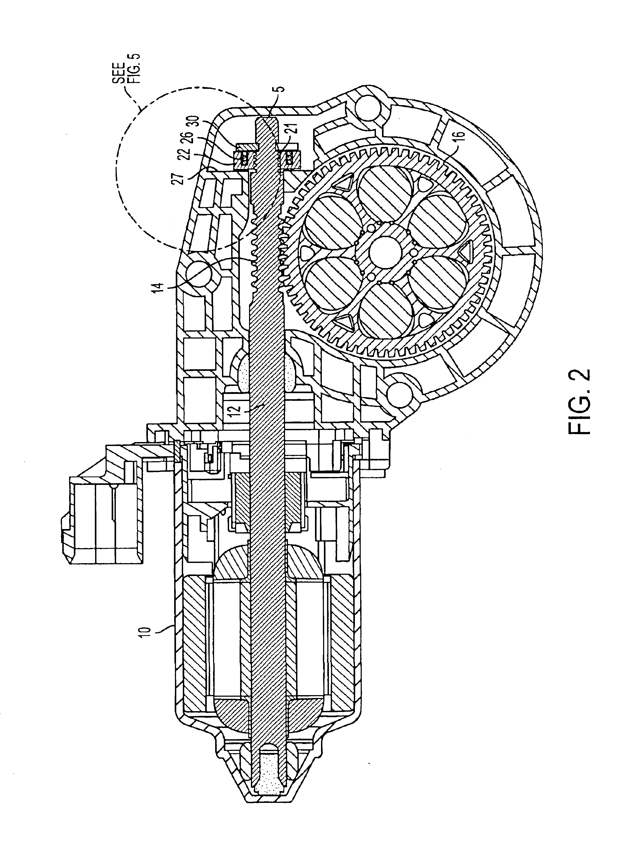
A clutch mechanism, for an electric motor 10, is shown generally indicated at 20 in FIG. 1, in accordance with the principles of the present invention. The motor 10 includes a shaft 12 having a worm 14 that engages an output gear 16.

A single or multiple-start helix 21 is provided on the motor output shaft 12 in addition to the worm 14. The helix 21 is adjacent to a stop or shaft shoulder 23, the function of which will be explained below. The clutch mechanism 20 includes a generally cylindrical pressure plate 22. The pressure plate 22 has a central boss 25 with an opening defining a helical configuration 24 that mates with the helix 21 of the shaft 12, so that the pressure plate 22 is movable along the axis A of the shaft 12. As shown in FIGS. 2-7, the pressure plate 22 is operatively associated with a friction surface 27 that is preferably part of the housing of motor 10.

A single compression spring 26 is disposed about the boss 25 of the pressure plate 22 within a recess 28 and bias...


PUM


Abstract

A clutch mechanism 20 is provided for a motor 10. The motor has a shaft 12, a worm 14 associated with the shaft, a gear 16 engaged by the worm, and a friction surface 27. The clutch mechanism 20 includes a pressure plate 22 mounted for movement with respect to the shaft toward and away from the friction surface 27. A spring 26 is constructed and arranged to bias the pressure plate towards the friction surface. A stop 30 is constructed and arranged to limit movement of the pressure plate in a direction away from the friction surface. Whereby, under a back drive condition of the motor when the motor is not energized and the gear is moved by an externally applied torque causing an axial force to be exerted on the worm inducing an axial and an angular movement to the shaft, the pressure plate is constructed and arranged to move towards and engage the friction surface thereby impeding rotation of the shaft.

Description

The invention relates to a unidirectional clutch mechanism for electric motors that becomes operational (engages) in one axial and one angular shaft direction.The purpose of this mechanism is to prevent a worm and gear in a motor from being back driven in the event that an external torque is applied at the output end of a gear arrangement. Currently this function is achieved by decreasing the gearing efficiency; however, the negative effect is that the overall system efficiency is decreased as well, possibly requiring a larger motor. By selectively having the ability to lock the system worm and gear, the gearing efficiency can be optimized to a higher level without major concerns for back drive.Current systems with similar functionality are based on the overrunning clutch drive configuration with an added taper to the shaft, so axial and radial engagements are selectively accomplished. These configurations are comprised of numerous small components that add cost to the system.Thus, ...

Claims


Application Information

Patent Timeline
Patent Type & Authority Patents(United States)
IPC IPC(8): H02K7/10H02K7/102H02K7/116H02K7/108E05F15/16F16H1/16
CPCH02K7/102H02K7/1166H02K7/108E05Y2900/55F16H1/16E05F15/697Y10T74/19637Y10T74/19828
Inventor ACOSTA, LUIS E.
Owner RPX CORP
Why Eureka
Try Eureka