

Synthetic resin container bearing label
a technology of synthetic resin and container, applied in the field of synthetic resin container, can solve problems such as cracking on the portion
- Summary
- Abstract
- Description
- Claims
- Application Information
AI Technical Summary
Benefits of technology
Problems solved by technology
Method used
Image

Examples
first embodiment
the present invention will be described in conjunction with accompanied drawings.
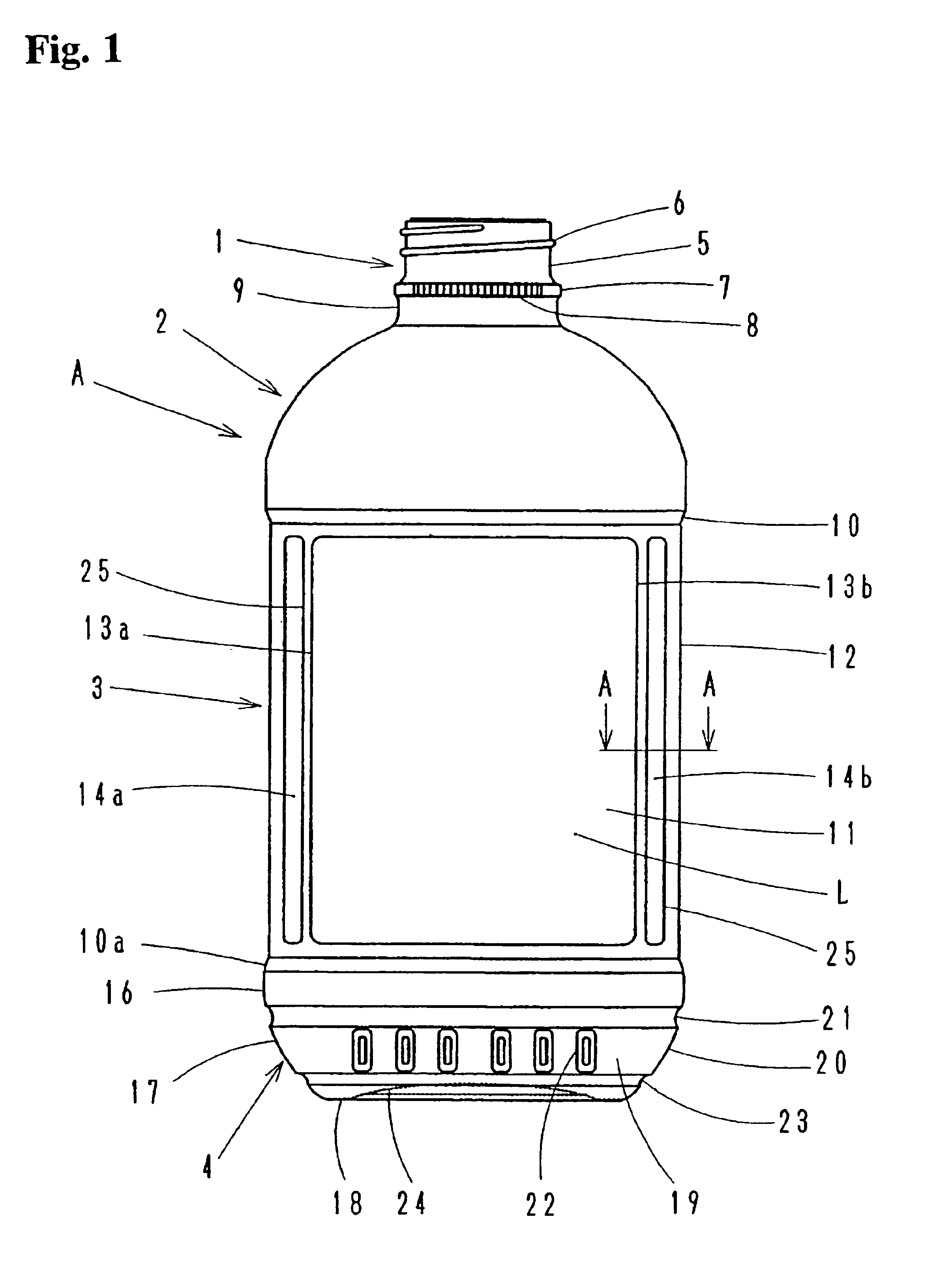
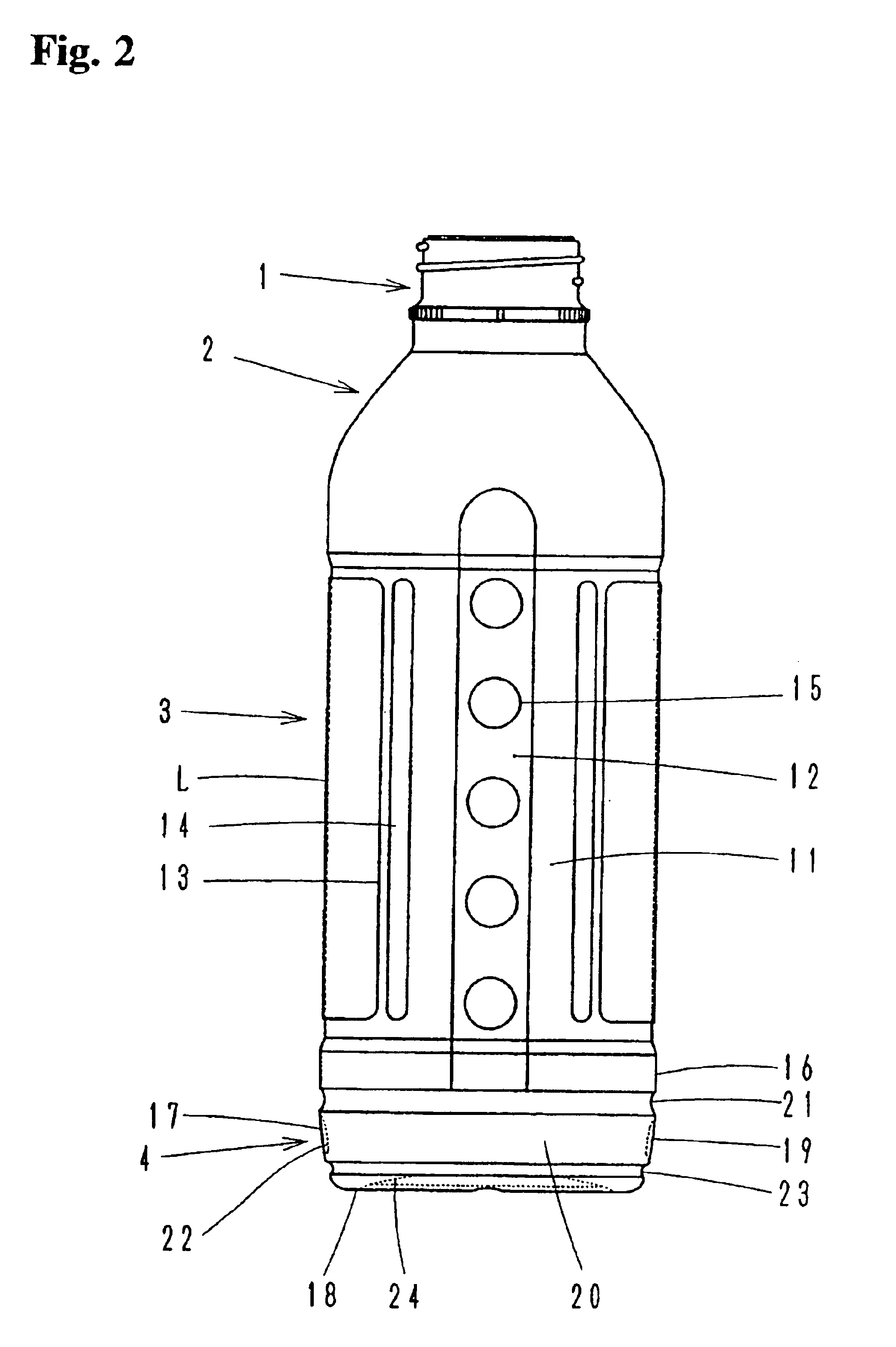
In FIGS. 1 and 2, a container “A” comprises a neck 1, a shoulder 2, a body 3 and a bottom 4, and is made of synthetic resin such as polyethylene (PE), polypropylene (PP) and other synthetic resin which is blow molded in a single layer or a laminated layer.
A screw 6 is threaded on an outer peripheral surface of an upper portion 5 of the neck 1. A holder ring 7 is provided below the screw.
A knurl 8 is provided partially or full circumference of an outer peripheral surface of the ring 7. A lower cylindrical neck 9 below the ring 7 has a larger diameter than that of the upper cylindrical neck 5, and is connected to the shoulder 2.
A step 10 is formed between the shoulder 2 and the body 3. The shoulder 2 and the body 3 has a flattened cross section, which comprises elliptical front and rear surfaces of front and rear walls 11, and a planar side surfaces of left and right side walls 12.
Each of the front and re...
second embodiment
the present invention will be described hereinafter referring to drawings.
In the above described first embodiment, the vertical ribs are arranged respectively along left and right edges of the label. On the other hand, in the second embodiment, vertical ribs and lateral ribs are disposed to surround full peripheral circumference of label edge. In the following explanation, relating to components of the second embodiment same as those of the first embodiment, suffix “a” is attached to respective numerals, to prevent the repeat of the explanation. The differences between the first and the second embodiments will be described mainly hereinafter.
In FIG. 7, a synthetic resin container “Aa” comprises a neck 1a, a shoulder 2a, a body 3a and a bottom 4a.
The body 3a comprises front and rear walls 11a, and left and right side walls 12a.
Each of the front and rear walls 11a is provided with lateral ribs 41a, 41b along upper and lower edges 40a, 40b of a label “La”, respectively, and with vert...
third embodiment
the present invention will be described by referring to the accompanied drawings.
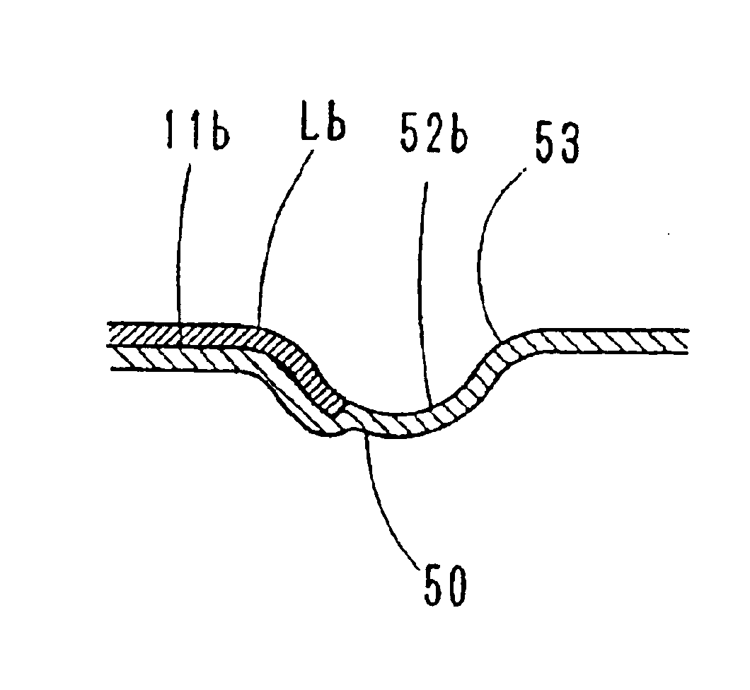
In this embodiment, the label edge is located in or reaches to the rib. In the following explanation, relating to components of the third embodiment same as those of the first embodiment, suffix “b” is attached to respective numerals, to prevent the repeat of the explanation. The differences will be described mainly hereinafter.
In FIGS. 8 and 9, a container “Ab” made of synthetic resin comprises a neck 1b, a shoulder 2b, a body 3b and a bottom 4b.
The body 3b comprises front and rear walls 11b, and left and right side walls 12b. The body 3b has a flattened cross section, which comprises elliptical front and rear surfaces of front and rear walls 11b, and planar side surfaces of left and right side walls 12b.
Each of the front and rear walls 11b is provided with lateral ribs 51a, 51b along upper and lower edges 50a of a label “Lb”, and with vertical ribs 52a, 52b along right and left edges 50b of the labe...
PUM
| Property | Measurement | Unit |
|---|---|---|
| thickness | aaaaa | aaaaa |
| thickness | aaaaa | aaaaa |
| thick | aaaaa | aaaaa |
Abstract
Description
Claims
Application Information