Rotary damper

a technology of rotary dampers and dampers, which is applied in the direction of shock absorbers, braking systems, transportation and packaging, etc., can solve problems such as affecting the stability of braking force, and achieve the effect of providing braking force in a more stable form

Inactive Publication Date: 2005-01-11
PIOLAX CO LTD
View PDF18 Cites 49 Cited by
  • Summary
  • Abstract
  • Description
  • Claims
  • Application Information

AI Technical Summary

Benefits of technology

This invention further contemplates forming an annular plain groove on the outer periphery of the rotor and setting in the plain groove an O-ring that is the braking member. Since the O-ring as the braking member is set in the plain groove of the rotor, it has no possibility of accidentally dropping off the rotor, and the braking force can be provided in a

Problems solved by technology

When the rotor integral with the gear is disposed within the holding chamber of the housing, however, it will readily incline

Method used


Image

  • Rotary damper
  • Rotary damper
  • Rotary damper

Examples


Embodiment Construction

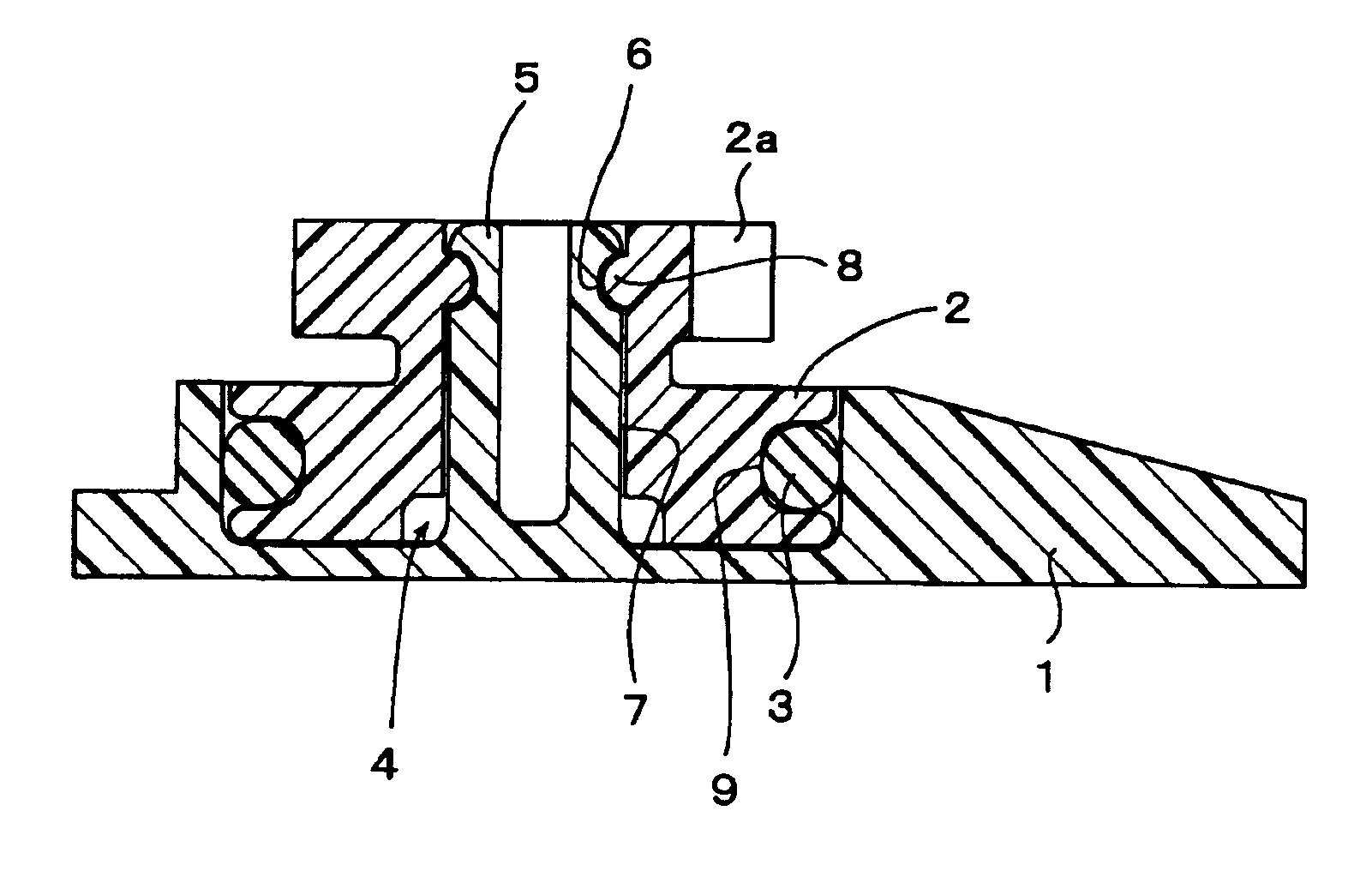
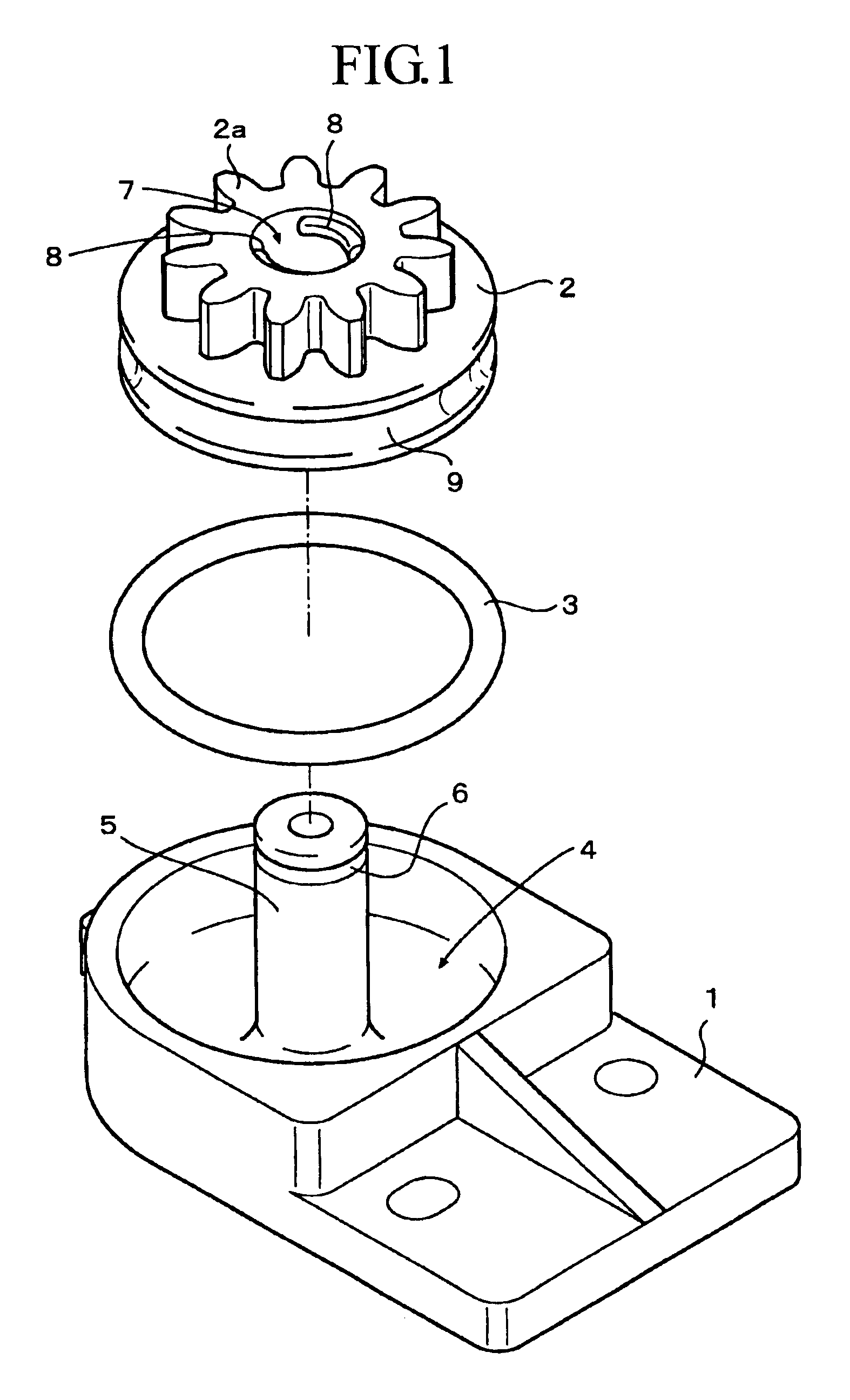
This invention will be described in detail below with reference to preferred embodiments illustrated in the drawings. A rotary damper according to one embodiment comprises three parts as illustrated in FIG. 1. A housing 1 has a holding chamber 4 open on one surface side. A rotor 2 is integral with a gear 2a that is disposed rotatably in the holding chamber 4 of the housing 1. An O-ring 3 constitutes a braking member for controlling the rotation of the rotor 2.

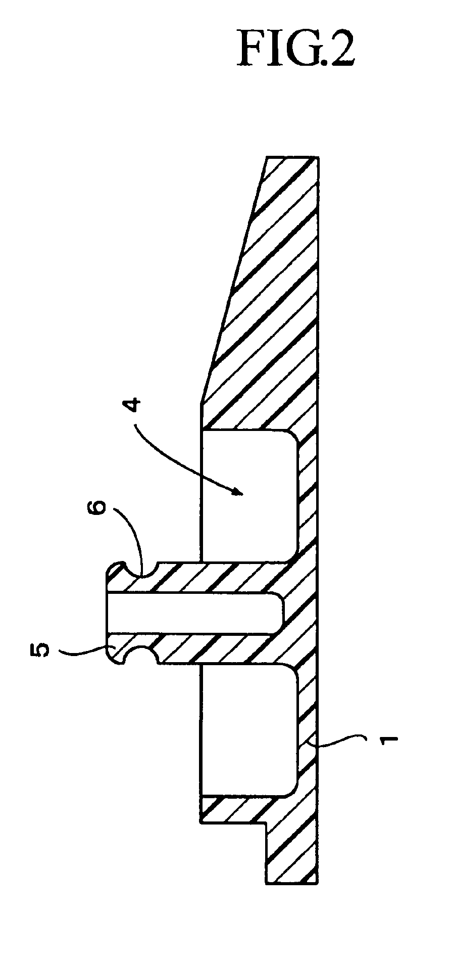
In the present embodiment, the housing 1 has a supporting shaft 5 erected at the center of the bottom part of the holding chamber 4, and has an annular locking groove 6 (i.e., an engagement member) formed in the leading terminal part (distal end) of the supporting shaft 5 as illustrated in FIG. 2. As illustrated in FIG. 3, the rotor 2 integral with the gear 2a has a shaft through-hole 7 bored therein for permitting insertion therethrough of the supporting shaft 5 inclusive of the integrating gear 2a in the axial direction there...


PUM


Abstract

A rotary damper includes a housing (1) that has a holding chamber (4), a rotor (2) integral with a gear (2a) disposed rotatably in the holding chamber (4) of the housing (1), and a braking member (3) for controlling the rotation of the rotor (2). The braking member (3) is interposed between the outer periphery of the rotor (2) and the inner periphery the holding chamber (4). A supporting shaft (5) is erected on the bottom part of the holding chamber (4) of the housing (1). A through-hole (7) is bored in the rotor for permitting insertion therein of the supporting shaft (5) in the axial direction of the rotor (2). The rotor (2) is supported through the supporting shaft (5) and the through-hole (7). With this configuration, a stabilized braking force is constantly provided because the rotor (2) does not incline it is being rotated.

Description

TECHNICAL FIELDThis invention relates to improvements in and concerning a rotary damper to be used in a push-open ashtray in an automobile, for example.BACKGROUND ARTThe damper illustrated in FIG. 2 of JP-A HEI 7-98035 has heretofore been known as belonging in this class of dampers.The conventional rotary damper, though not specifically illustrated herein, is provided with a housing that has a holding chamber. It is further provided with a rotor integral with a gear, which rotor is disposed rotatably in the holding chamber of the housing, and a braking sheet interposed between the bottom part of the holding chamber of the housing and the lower surface of the rotor. It is so constructed that it enables application of the braking force to the speed of opening the push-open ashtray by utilizing the frictional resistance generated between the rotor and the braking sheet due to the sliding rotation of the rotor on the braking sheet.The conventional rotary damper is used to control the pu...

Claims


Application Information

Patent Timeline
IPC IPC(8): F16F9/12F16F9/10F16F7/00F16F7/06
CPCF16F9/12F16F7/06F16F7/04
Inventor ARISAKA, OOMI
Owner PIOLAX CO LTD
Why Eureka
Try Eureka