Magnetic head slider and disk drive with reduced damage to recording medium

Inactive Publication Date: 2006-06-29
WESTERN DIGITAL TECH INC
View PDF15 Cites 15 Cited by
  • Summary
  • Abstract
  • Description
  • Claims
  • Application Information

AI Technical Summary

Benefits of technology

[0022] The magnetic head slider mounted in the disk drive includes the damage preventive protective film having a smaller coefficient of friction so as not to generate a large friction force when the slider comes into contact with the disk. Accordingly, it is possible to provide a disk drive offering a high reliability against vibration or the like, since damage to the disk can

Problems solved by technology

Consequently, the slider tends to drag as the slider is in contact with a spinning disk recording medium.
It is then

Method used


Image

  • Magnetic head slider and disk drive with reduced damage to recording medium
  • Magnetic head slider and disk drive with reduced damage to recording medium
  • Magnetic head slider and disk drive with reduced damage to recording medium

Examples


first embodiment

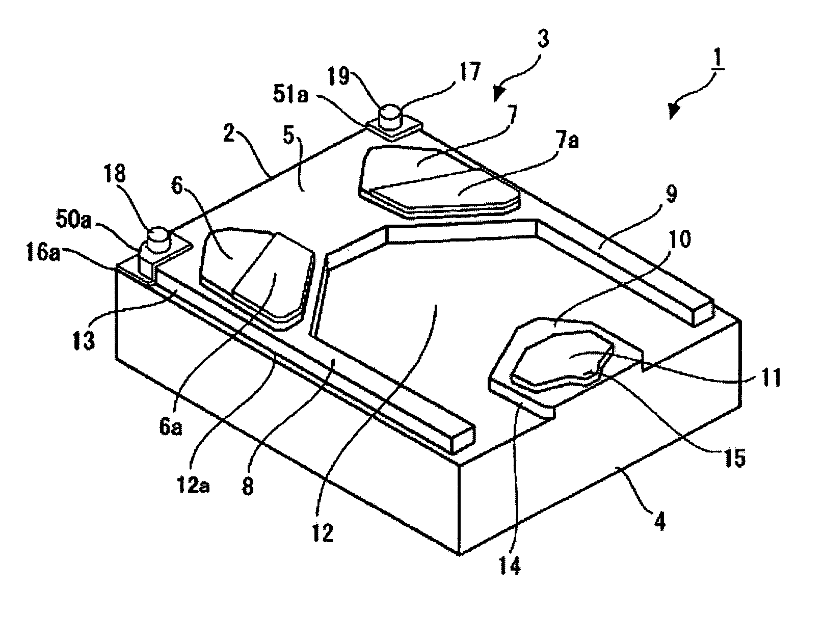
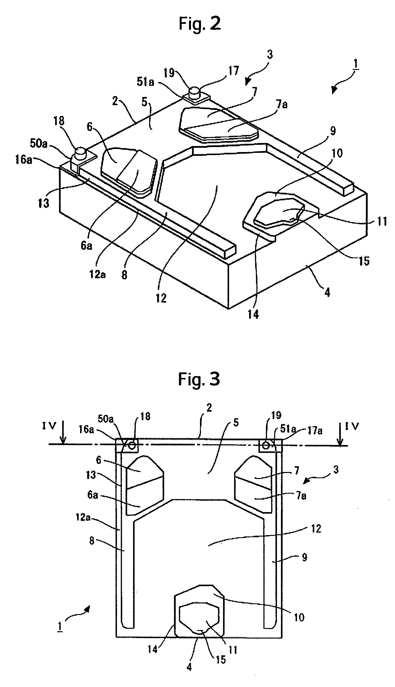
[0059] The magnetic head slider 1 includes a magnetic transducer 15 for writing / reading information to / from the disk recording medium. The magnetic transducer 15 is provided on the trailing side rail surface 11 of the rear pad 14. The magnetic head slider 1 according to the present invention also includes leading pads 18, 19. The leading pads 18, 19 are of the same height as the leading side rail surfaces 6, 7. The leading pads 18, 19 are respectively located at points near vertices of slider corners on the side of the leading end 2 on the side of the ABS 3. In addition, the magnetic head slider 1 is provided with deep grooves 12a on both ends in the slider longitudinal direction of the front pad 13. The deep grooves 12a are as deep as the deep groove surface 12. The deep grooves 12a are formed at the same time when the deep groove surface 12 is formed as part of machining the magnetic head slider 1. The machining method for the magnetic head slider 1 will be described later.

[0060] ...

second embodiment

[0099] In the second embodiment, step surfaces 6a, 7a may be formed simultaneously with the trailing corner carbon protective films 50b, 51b as described above as well. This allows the magnetic head slider 61 ensuring a stabilized flying height even under low pressure conditions without involving an increase in the manufacturing cost.

[0100] A magnetic head slider according to a third embodiment of the present invention will be described. FIGS. 12 and 13 are a perspective view and a plan view, respectively, showing the magnetic head slider according to the third embodiment of the present invention. A magnetic head slider 62 according to the third embodiment of the present invention includes leading corner carbon protective films 50a, 51a and trailing corner carbon protective films 50b, 51b according to the first and second embodiment, respectively. This arrangement achieves the effects of both the first and the second embodiments of the present invention. It can be said that the magn...

fifth embodiment

[0104] The fifth embodiment is effective in reducing disk damage caused by vibration in the roll direction as well as the pitch direction particularly in the case where the flying height on the side of a leading end 2 is greater than that on the side of the trailing end 4 and the magnetic head slider 64 rises in the slider longitudinal direction.

[0105]FIGS. 16 and 17 are plan views showing a magnetic head slider according to sixth and seventh embodiments of the present invention, respectively. Each of the magnetic head sliders according to the sixth and the seventh embodiment differs from the magnetic head slider 1 of the first embodiment in that an ABS 3b has short side step bearing surfaces 8, 9. Magnetic head sliders 65, 66 having such short side step bearing surfaces 8, 9 have a characteristic that makes small dependence thereof on a rotational speed of the disk recording medium 101.

[0106] The magnetic head slider 65 has trailing corner carbon protective films 51c, 51e on regio...


PUM


Abstract

Embodiments of the invention reduce damage to a disk recording medium when a slider flying above the disk recording medium inside a magnetic disk drive comes into contact with the disk recording medium due to slider vibration. In one embodiment, a magnetic head slider includes a front pad, a rear pad, and carbon protective films. The front pad includes a step bearing surface disposed on the side of a leading end and leading side rail surfaces formed on the step bearing surface. The rear pad includes a rear step bearing surface disposed across a deep groove surface from the front pad and a trailing side rail surface formed on the rear step bearing surface. The carbon protective films are formed on regions including vertices of slider corner portions, respectively. The leading side rail surfaces and the trailing side rail surface are formed substantially on the same level. The carbon protective films are harder than a slider base material and have a small coefficient of friction. The films have a film thickness of about 10 nm or more.

Description

CROSS-REFERENCES TO RELATED APPLICATIONS [0001] This application claims priority from Japanese Patent Application No. JP2004-377829, filed Dec. 27, 2004, the full disclosure of which is incorporated herein by reference. BACKGROUND OF THE INVENTION [0002] The present invention relates to a magnetic head slider in which measures are taken for reducing damage to a disk recording medium that could otherwise be caused when the magnetic head slider comes into contact with the disk recording medium as a result of vibration of the slider produced from disturbance. The present invention also relates to a disk drive mounted with the magnetic head slider. [0003] A magnetic disk drive uses a magnetic head slider that flies above a spinning disk recording medium, while maintaining a microscopic distance (a flying height) therefrom. In general the magnetic head slider is provided at its trailing end with a magnetic transducer for reading and writing information from and to the disk recording medi...

Claims


Application Information

Patent Timeline
IPC IPC(8): G11B5/60
CPCG11B5/40G11B5/6005G11B5/3106G11B5/6082
Inventor HASHIMOTO, KIYOSHIKOHIRA, HIDEKAZUYAMAZAKI, TAKANORIMIYAKE, KOJI
Owner WESTERN DIGITAL TECH INC
Why Eureka
Try Eureka