Rocker arm

a technology of rocker arm and guide surface, which is applied in the direction of valve arrangement, machines/engines, mechanical equipment, etc., can solve the problem of small friction area between the guide surface and the valve stem, and achieve the effect of excellent reliability and durability

Inactive Publication Date: 2005-02-17
NSK LTD
View PDF2 Cites 3 Cited by
  • Summary
  • Abstract
  • Description
  • Claims
  • Application Information

AI Technical Summary

Benefits of technology

[0024] Taking the above problems into consideration, an object of this invention is to keep the friction force acting on the point of contact between the outer peripheral surface of the valve and the guide surfaces small.
[0026] In the case of the rocker arm according to this first feature of the invention, when the base end section of the valve stem moves in the width direction of the fitting surface, so that the outer peripheral surface of this base end section comes in contact with on either of the guide surfaces, the area of the point of contact between these surfaces becomes narrow, or in other words, the length of the point of contact in the axial direction of the valve stem becomes short. Therefore, even when both the valve stem and rocker arm rock and move relative to each other, it is possible to keep the friction force acting on the point of contact between these surfaces small. In other words, since the length of the point of contact in the axial direction of the valve stem is short, it is possible to improve the lubricity of the point of contact and keep the friction force per unit area small, as well as it is possible to keep small the moment of the friction resistance that acts at this point of contact. As a result, it becomes easier to keep small the resistance that occurs at the fitting section between the rocker arm and the valve stem and to improve the performance of the engine.
[0028] In the case of the rocker arm according to this second feature of the invention, there is no tensile stress in or near the side-wall sections or guide-wall sections, and the space between the pair of guide-wall sections that are located on both sides of the connecting section that comes in contact with the base end section of the valve stem can be changed to correspond to the diameter of the base end section of the valve stem. Therefore, it is possible to make the fitting with the base end section of the valve stem more suitable, and to make a rocker arm that has excellent reliability and durability.

Problems solved by technology

Moreover, by making these guide surfaces unparallel such that the space between the guide surfaces on the side away from the fitting surface along the center axis of the valve stem is more narrow than the space on the side near the fitting surface, the friction area between the guide surfaces and the valve stem is kept small.

Method used


Image

  • Rocker arm
  • Rocker arm
  • Rocker arm

Examples


first embodiment

[0056] The other construction and function is substantially the same as that of the first embodiment, so any redundant explanation is omitted.

[0057] In the case of the rocker arm that is constructed and functions as described above, it is possible to keep the friction at the fit between the rocker arm and valve small, and to increase the performance of the engine in which this rocker arm is installed.

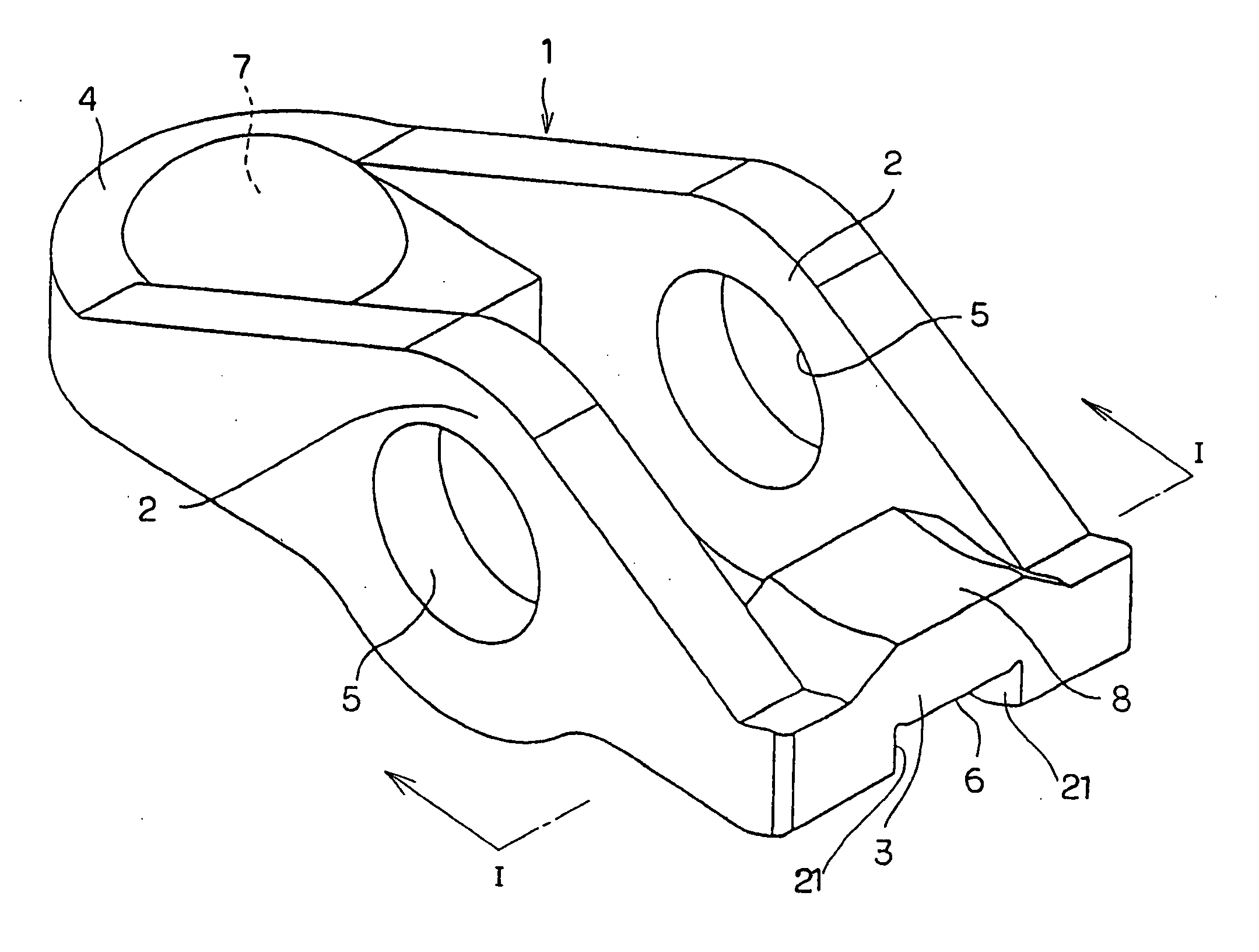
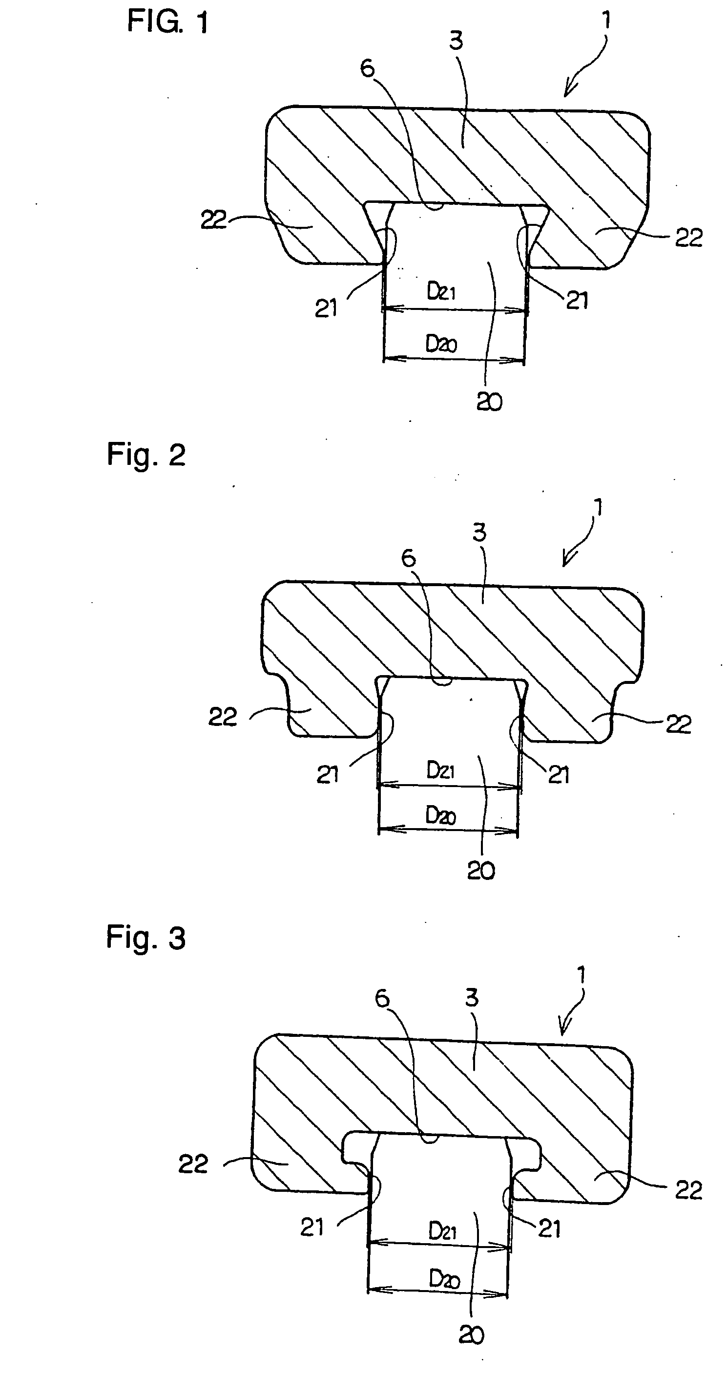
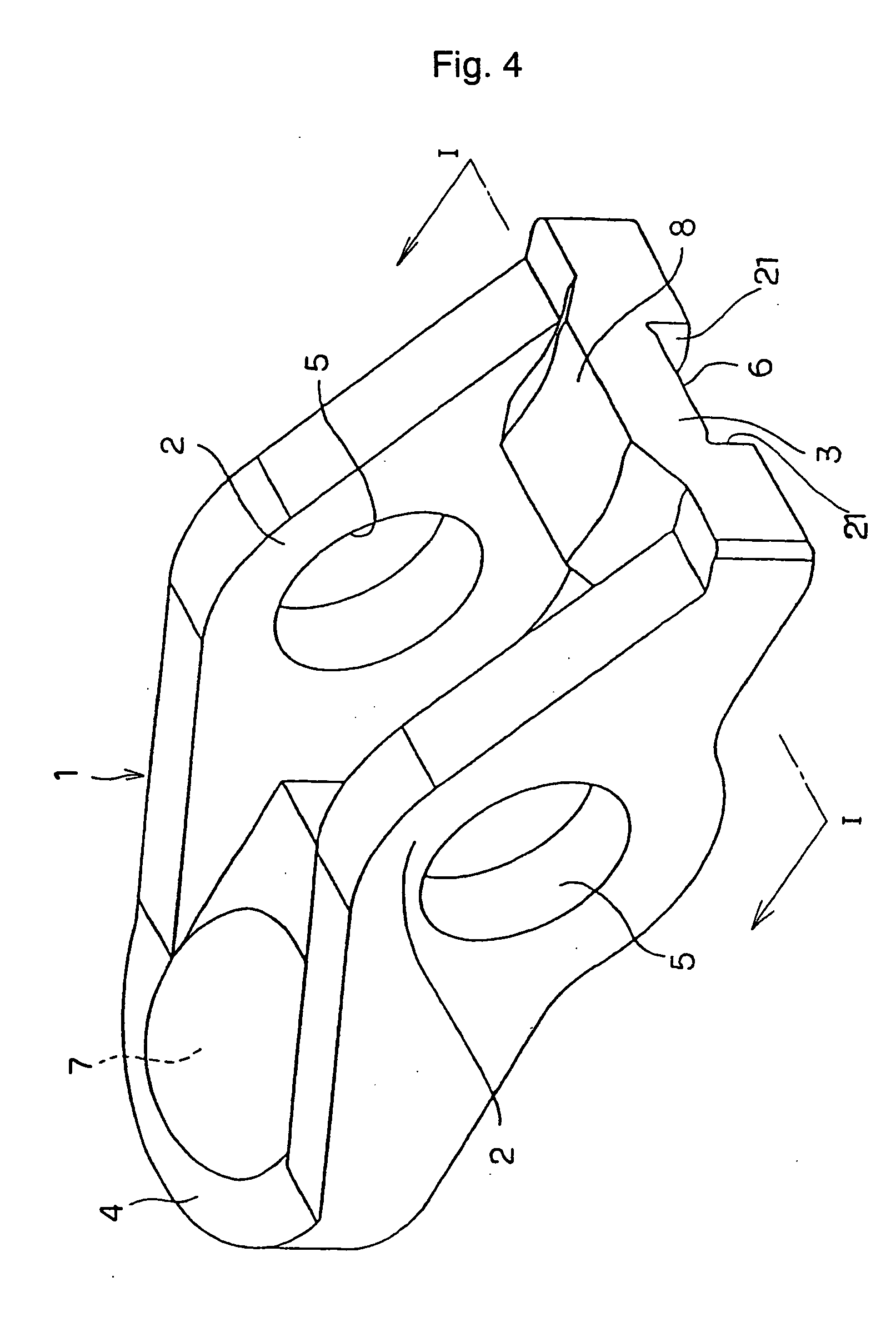
[0058] FIGS. 11 to 13 show a fourth example of the embodiment of the invention. A feature of this example is to prevent large tensile stress, which causes damage such as cracking, from being applied to and near a pair of guide-wall sections 21, and to make a suitable fit between the rocker arm 1 and valve stem 20 by tailoring the shape of this pair of guide-wall sections 21 that are formed on both ends in the width direction of one surface of the connecting section 3 of the rocker arm 1 such that they are located on both sides in the width direction of the fitting surface 6. The constr...

seventh embodiment

[0069] The other construction and functions are substantially the same as those of the seventh embodiment described above, so any redundant explanation is omitted.

Industrial Applicability

[0070] With the rocker arm that is constructed and functions as described above can be manufactured at low cost by performing plastic working such as pressing or punching of a metal plate, and it is possible to obtain a rocker arm that has a good fit with the base end section of the valve, and which also has excellent reliability and durability.


PUM


Abstract

The rocker arm 1 has a fitting surface 6 on the opposite sides of which guide surfaces 21 are formed, such that the guide surfaces 21 are inclined to be closer to each other toward their tip ends. Even when the valve stem 20 is displaced in the widthwise direction of the fitting surface 6, the outer peripheral surface of the base end portion of the valve stem 20 comes into contact with only the tip end of one of the guide surfaces 21. Consequently, lubrication is improved and friction moment is decreased in the contact area, so that friction resistance is suppressed between the guide surfaces 21 and the outer peripheral surface of the base end of the valve stem 20 to easily obtain high performance of the engine.

Description

TECHNICAL FIELD OF THE INVENTION [0001] This invention relates to improvements for converting the rotation of the camshaft assembled in the valve gear of an engine to reciprocating motion of a valve stem (air intake valve and exhaust valve). BACKGROUND OF THE INVENTION [0002] In a reciprocating engine (reciprocating-piston engine), except for some 2-cycle engines, there are air-intake valves and exhaust valves that open and close in synchronization with the rotation of the crankshaft. In this kind of reciprocating engine, the movement of the camshaft that rotates in synchronization with the rotation of the crankshaft (½ the rpm in the case of a 4-cycle engine) is transmitted to the air-intake valves and exhaust valves by rocker arms, and causes the air-intake valves and exhaust valves to move in a reciprocating motion in the axial direction. [0003] Conventionally, castings (cast iron parts or aluminum die-cast parts) were used for the rocker arm assembled in the valve gear of this k...

Claims


Application Information

Patent Timeline
Patent Type & Authority Applications(United States)
IPC IPC(8): F01L1/18
CPCB21K1/205F01L1/185F01L2105/02F01L2103/00F01L2105/00F01L2101/00F01L2305/02F01L2301/00F01L2303/00F01L2305/00
Inventor TAKEO, NORIYUKIGOTOU, KAZUSHIGEKADOKAWA, SATOSHI
Owner NSK LTD
Why Eureka
Try Eureka