
Dynamic sealing device

a sealing device and dynamic technology, applied in the direction of engine seals, mechanical devices, engine components, etc., can solve the problems of friction on the seal, and achieve the effect of limiting the premature wear of such a device and improving performan

Active Publication Date: 2019-03-21
ETI GRP
View PDF4 Cites 3 Cited by
  • Summary
  • Abstract
  • Description
  • Claims
  • Application Information

AI Technical Summary

Benefits of technology

The invention describes a device that has a better resistance to high pressures and temperatures than previous devices. It uses a seal and a ring that can withstand small friction forces. The ring is securely connected to the seal using a specific method that reduces friction and improves the device's ability to resist wear and tear. This makes the device more durable and reliable. Overall, the invention provides a better sealing device that can withstand higher pressures and temperatures while reducing friction and wear.

Problems solved by technology

Such sliding gives rise to a phenomenon of friction on the seal.

Method used


Image

  • Dynamic sealing device
  • Dynamic sealing device
  • Dynamic sealing device

Examples


Embodiment Construction

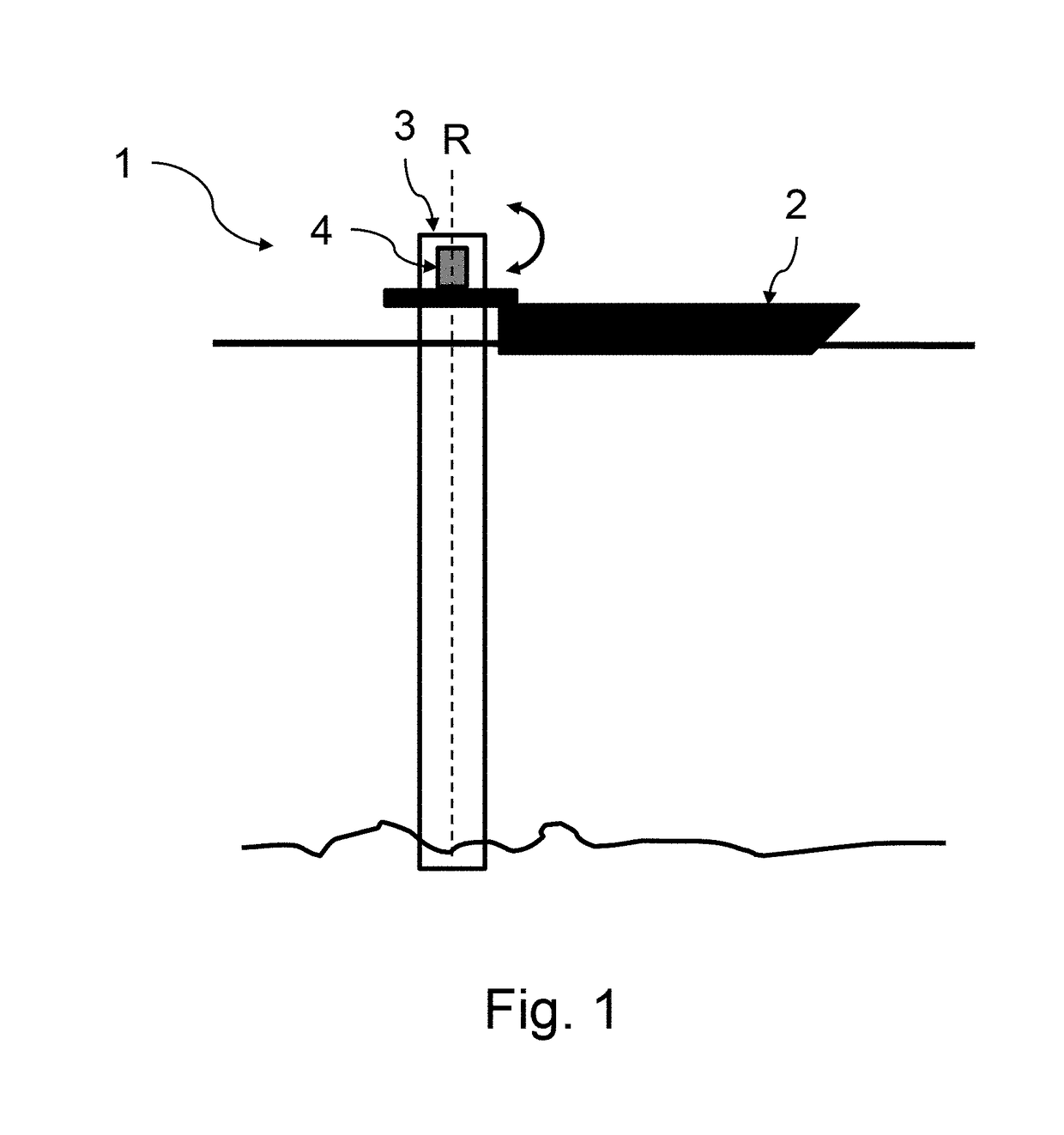
[0033]FIG. 1 diagrammatically and partially represents a floating production unit 1, comprising a ship 2 and a mooring turret 3.

[0034]The turret 3 is mechanically connected here to a platform extending from the ship 2. The turret 3 is fixed whereas the ship 2 is able to turn around the turret 3. The ship is thus rotationally movable around the axis R represented in FIG. 1. Pipes (not shown) forming a network of subaquatic ducts enable fluidic communication for the transfer of a fluid between the turret 3 and the ship 2.

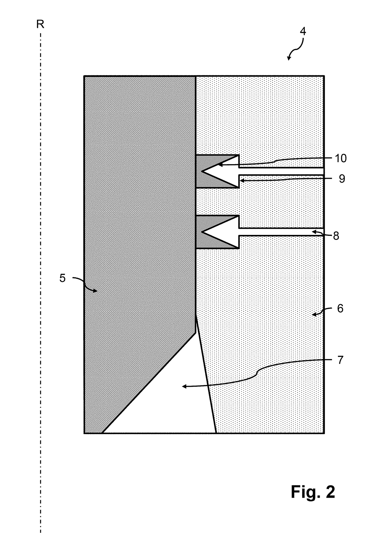
[0035]To provide sealing between the ship 2 and the turret 3 and thereby provide the integrity of the fluid transfer, a mechanism 4, also called swivel joint, is interposed between a fixed member (also called first member) of the turret 3 and a movable member (also called second member) of the platform of the ship 2.

[0036]The mechanism 4 provides sealing during a transfer of fluid between the turret and the platform.

[0037]Electronic communications may also be provided...


PUM


Abstract

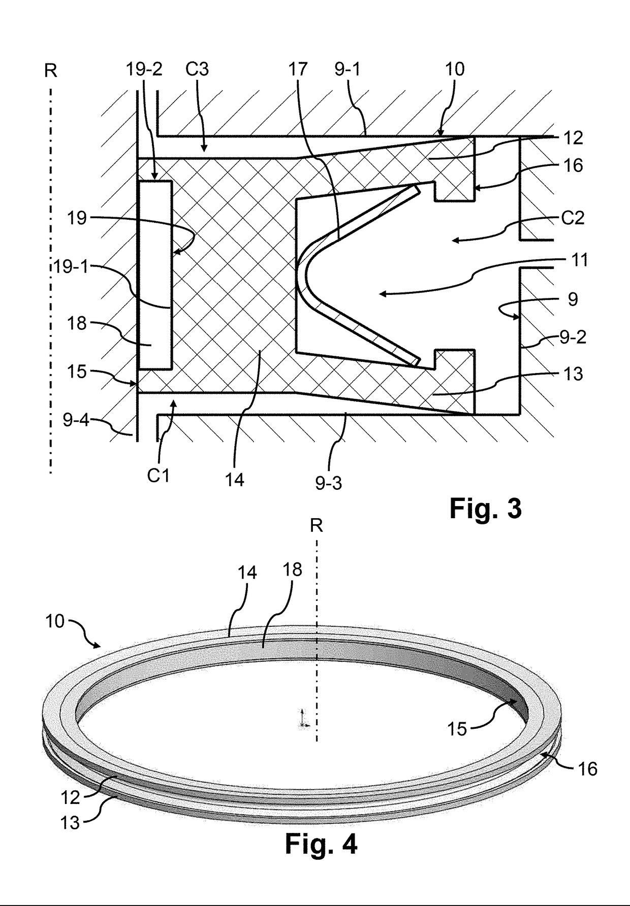
Disclosed is a dynamic sealing device configured to provide sealing between at least a first part and at least a second part having a relative rotational movement in relation to the first part. The device includes a seal provided with a first lip and with a second lip extending from a body portion, the first lip facing the second lip, the seal being formed from a first predetermined material having a first coefficient of friction, and a ring formed from a second predetermined material different from the first predetermined material and having a second coefficient of friction different from the first coefficient of friction. The ring is securely connected with the seal at the location of the body portion and the first coefficient of friction of the first predetermined material forming the seal is greater than the second coefficient of friction of the second predetermined material forming the ring.

Description

FIELD OF THE INVENTION[0001]The present invention concerns dynamic sealing devices configured to provide sealing between two parts having relative movement in relation to each other.TECHNOLOGICAL BACKGROUND[0002]Dynamic sealing devices installed in equipment under pressure, also called swivel joints, can have an application in petroleum production ships in the offshore field, enabling the exploitation of hydrocarbon fields at sea at depths which are sometimes very great. Floating production storage and offloading (FPSO) units are in general formed by a ship which is movable, on account of its environment, around a mooring turret, which is geostationary. The ship is generally secured temporarily to the turret and pipes forming a network of subaqueous ducts enable fluidic communication for the transfer of a fluid between the turret and the ship.[0003]To provide sealing between the ship and the turret and thereby provide the integrity of the fluid transfer, a dynamic sealing device may...

Claims


Application Information

Patent Timeline
IPC IPC(8): F16J15/3232
CPCF16J15/3232F16J15/3236
Inventor MATTONI, GAETANBERENGER, BRICE
Owner ETI GRP
Learn More