Trigger safety lock for pistols and trigger assembly

a safety lock and pistol technology, applied in the direction of safety arrangements, weapons, weapons, etc., can solve the problems of achieve the effect of preventing excessive wear of trigger materials and ensuring the engagement of locking pins

Inactive Publication Date: 2005-01-18
CUTINI JORGE ENRIQUE +1
View PDF21 Cites 28 Cited by
  • Summary
  • Abstract
  • Description
  • Claims
  • Application Information

AI Technical Summary

Benefits of technology

The carefully designed locking pin is inserted in a through-hole that is made on each side of the trigger and is longer than the trigger in itself so that it may be pushed by the user by pressing on the locking pin projecting out of one of the trigger's side, for locking the trigger assembly, and unlocking it by pressing on the opposite side. The locking pin shows two end ridged portions of greater diameter and two central portions of different diameters, both smaller than the end portions. The locking pin may also be useful for left handed users since insertion of the locking pin may easily be inverted for this use.
In a highly preferred embodiment, each of the different portions of the locking pin has circular cross section; however other alternative embodiments may consider the use of ellipsoid or elliptic cross sections or other geometric figures such as triangles, four sided figures and other polygons, all with rounded vertices. These alternative cross sections may offer a better locking pin engagement, avoiding a rotation around its symmetry axis but, at the same time, these cross section profiles may produce excessive trigger material wear-out.

Problems solved by technology

These alternative cross sections may offer a better locking pin engagement, avoiding a rotation around its symmetry axis but, at the same time, these cross section profiles may produce excessive trigger material wear-out.

Method used


Image

  • Trigger safety lock for pistols and trigger assembly
  • Trigger safety lock for pistols and trigger assembly
  • Trigger safety lock for pistols and trigger assembly

Examples


Embodiment Construction

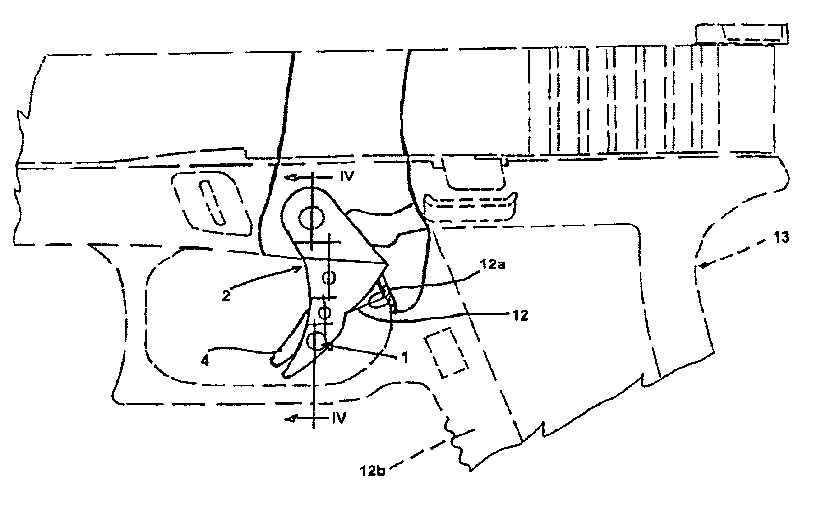
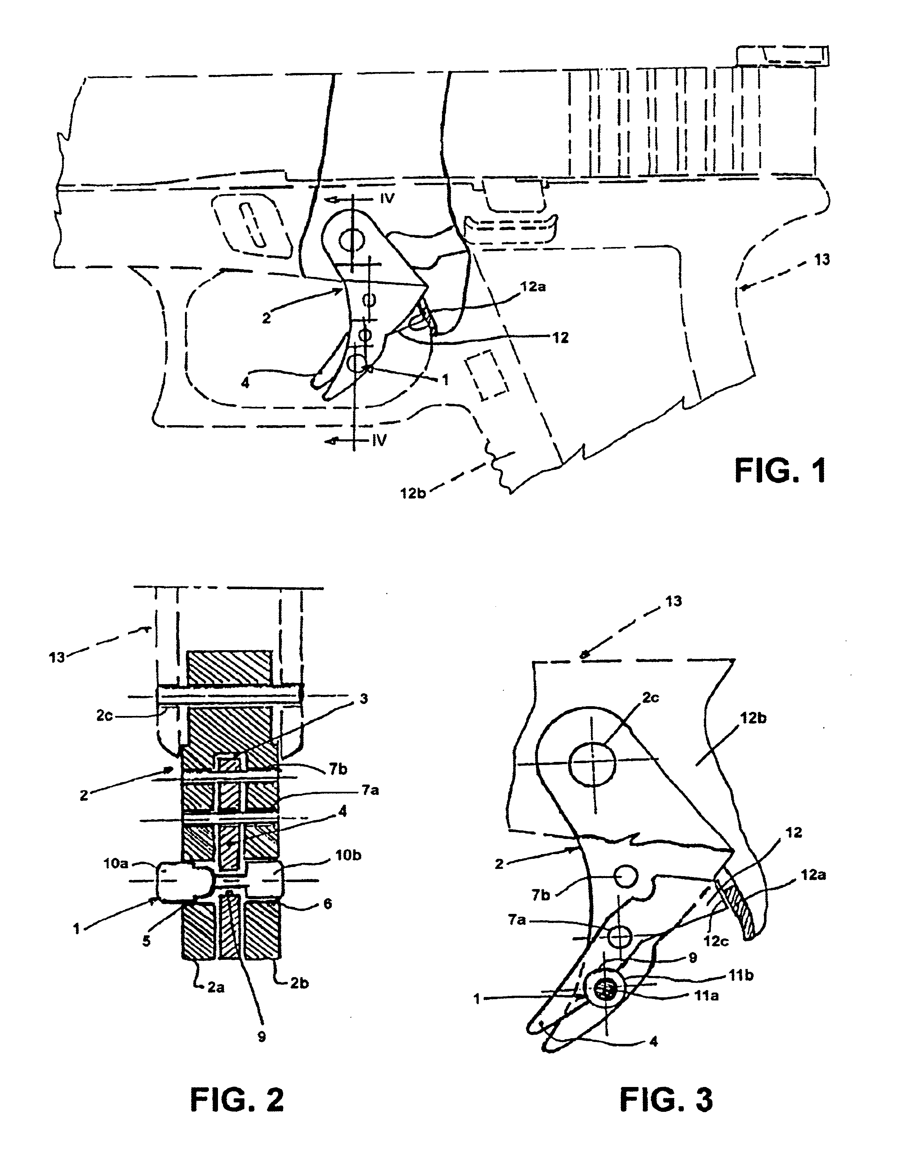
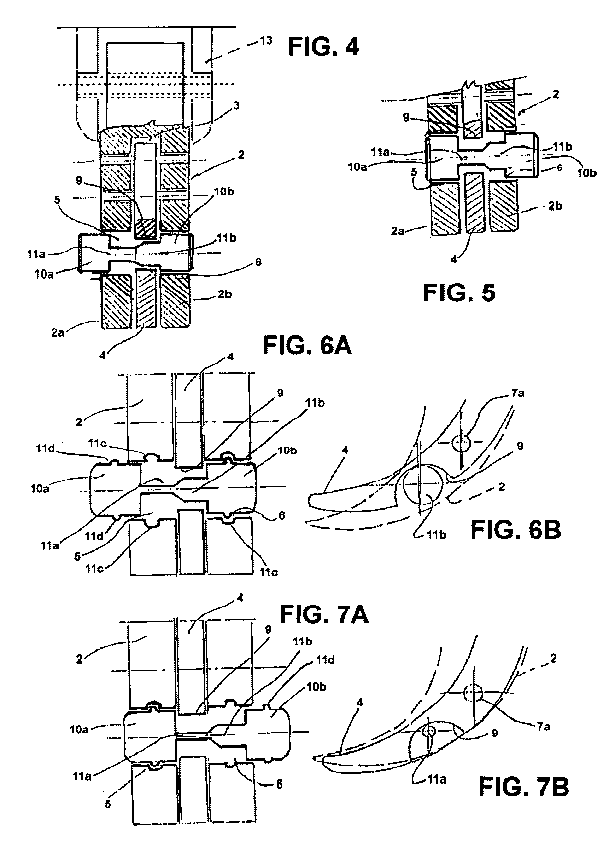
FIGS. 1, 2 and 3, show a pistol 13 comprising a (main) trigger 2 and a safety member (secondary trigger) 4 which may rotate around an axis 2c and also including a locking pin 1. In FIG. 2 it may be seen that the safety member 4 is housed inside a central cavity 3 inside the trigger 2, between trigger sides 2a and 2b.

For sake of clarity the trigger assembly of the prior art will now be described (i.e. the trigger assembly supplied by the manufacturer of the GLOCK® pistol).

In FIGS. 9A and 9B it is shown that the safety member may pivot around a rotation axis and the safety member comprises a rear blocking portion which, if the safety member is not pressed by the user, will lock the trigger assembly. This is achieved because, in a locking position, the rear wall of the rear portion abuts against the front wall of the pistol's hand grip. When the user presses on the trigger and on the safety member simultaneously, the trigger may rotate around its axis (in a counterclockwise direction)...


PUM


Abstract

A trigger assembly is adapted to replace the trigger and trigger safety assembly supplied in pistols for enhancing safety features. The invention is formed by a sideways insertable locking pin, a newly designed trigger safety member and a helicoidal spring. The user may lock the pistol trigger assembly by pushing the locking pin to one safe position, and unlock it with an opposite movement.

Description

RELATED DOCUMENTSThe present invention claims priority of Argentine Patent Application No. P02 01 01459, filed on Apr. 22, 2002 and Argentine Patent Application No. P03 01 01344, filed on Apr. 16, 2003.BACKGROUND OF THE INVENTIONThe present invention relates to a lock for trigger safety to be used in firearms triggers and a trigger assembly that contains the trigger safety lock, to be used particularly in hand held pistols. Preferably, the invention is to be applied, and is an improvement, to the safety mechanism used in pistols with brand GLOCK®, which will be called, for simplicity, from now on this document as the GLOCK® safety mechanism.The trigger safety lock of the present invention allows for adding safety features to the known GLOCK® safety mechanism, particularly in those cases in which the user is forced to walk through places of difficult access while holding the pistol in his hand. Obstacles such as figs, bushes, or any kind of interfering elements that may be found in c...

Claims


Application Information

Patent Timeline
Patent Type & Authority Patents(United States)
IPC IPC(8): F41A17/46F41A17/00
CPCF41A17/46
Inventor CUTINI, JORGE ENRIQUEMAREQUE, FERNANDO
Owner CUTINI JORGE ENRIQUE
Why Eureka
Try Eureka