

Elliptically polarized cavity backed wideband slot antenna
a wideband, cavity-backed technology, applied in the field of antennas, can solve the problems of insufficient address, difficult to achieve satisfactory broadband antenna performance, and limited performance to meet the industry expectations of these prior systems
- Summary
- Abstract
- Description
- Claims
- Application Information
AI Technical Summary
Benefits of technology
Problems solved by technology
Method used
Image

Examples
Embodiment Construction
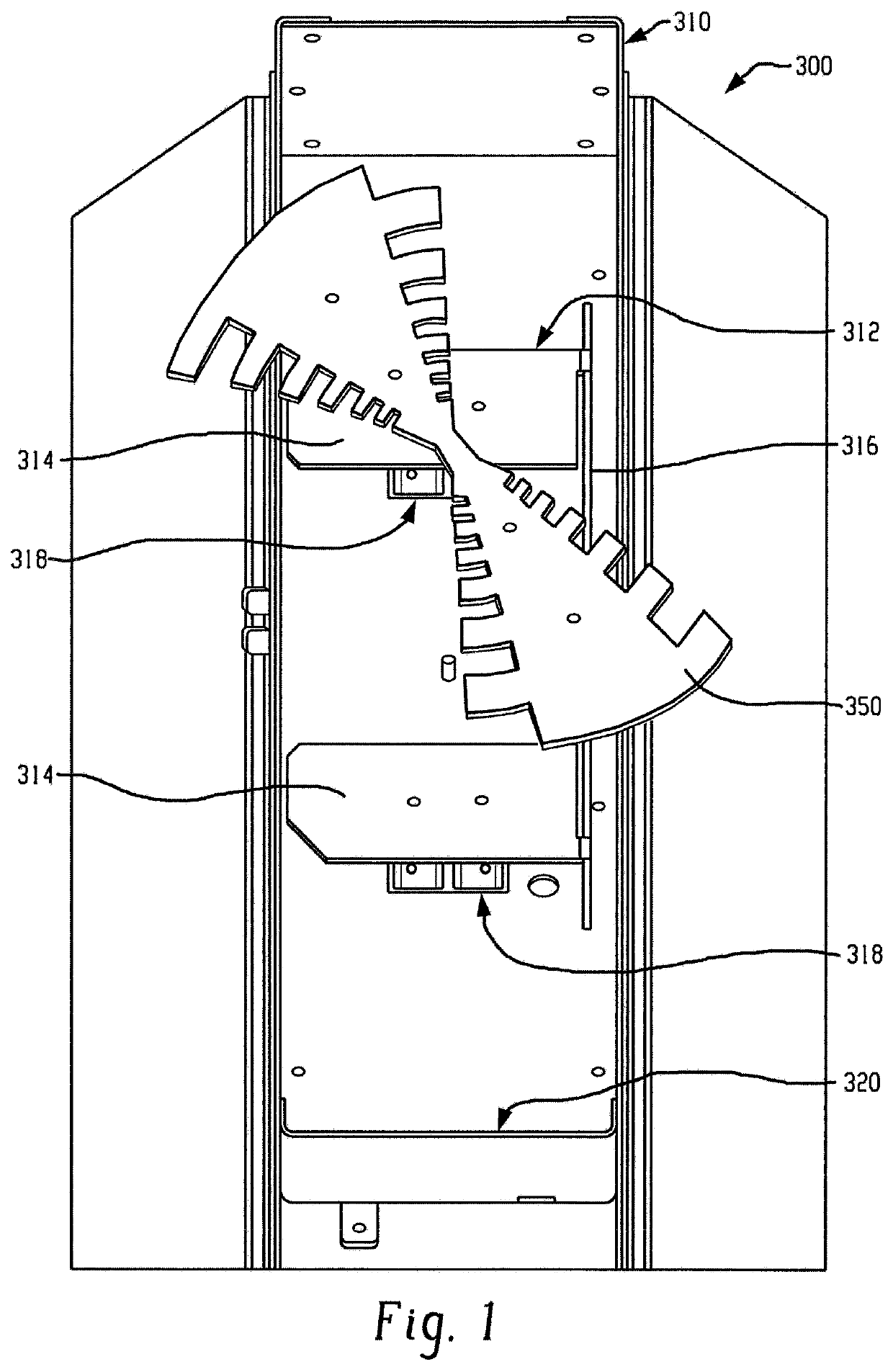
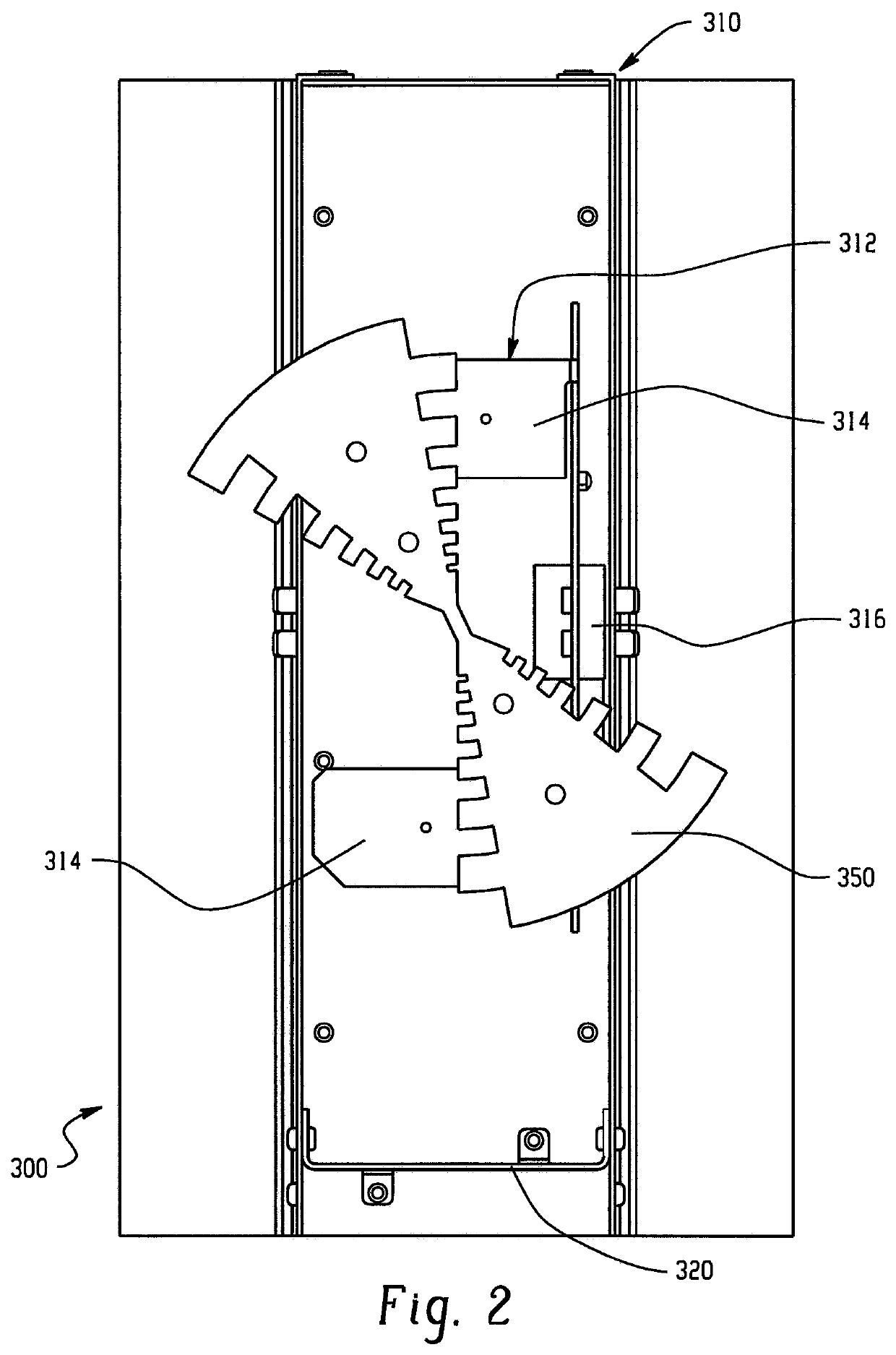
[0034]The presently described embodiments are directed to elliptically polarized cavity backed wideband slot antennas. An elliptically polarized cavity backed wideband slot antenna according to the presently described embodiments combines a horizontally polarized cavity backed slot antenna with a planar log periodic parasitic dipole. This combination of elements allows the antenna array to form a desired elliptically polarized radiation pattern.
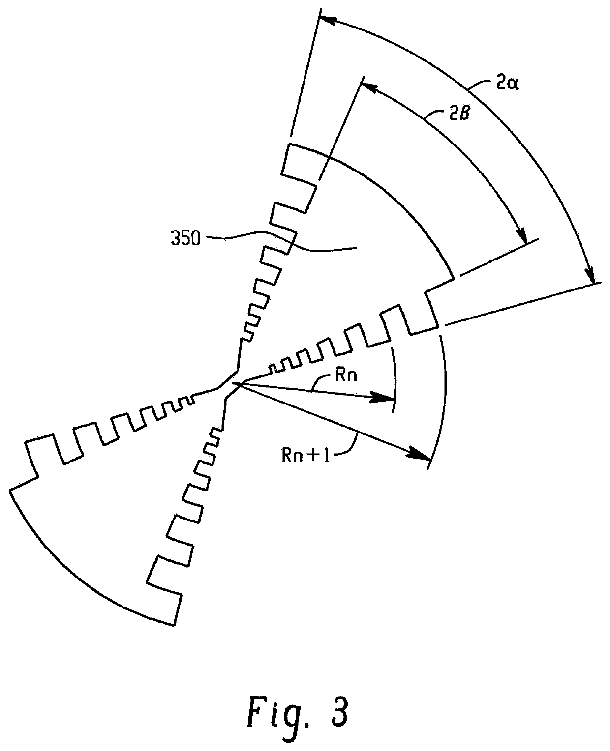
[0035]Implementation of the presently described embodiments results in advantages of obtaining large bandwidth with careful design of the dipole, e.g. the dipole angle and the dimensions of the teeth, providing constant E-field distribution, providing good impedance properties, and ensuring constant power ratio for both vertical and horizontal polarizations.
[0036]With reference to FIGS. 1 and 2, a portion of an antenna array 300 is shown. Some portions of the array are not shown for ease of observation and explanation. The array 300 includes ...
PUM
 Abstract
Description
Claims
Application Information