Weather strip including core-removal slot

a weather strip and core technology, applied in the field of weather strips, can solve the problems of increasing manufacturing costs, burdensome application of weather strip adhesives, and reducing the sealing capability of weather strips, and achieve the effect of high sealing capability and aesthetic appearan

Inactive Publication Date: 2005-01-18
TOYODA GOSEI CO LTD
View PDF12 Cites 88 Cited by
  • Summary
  • Abstract
  • Description
  • Claims
  • Application Information

AI Technical Summary

Benefits of technology

It is an object of the present invention to provide a weather strip having a high sealing capability and an aesthetic appearance when attached to a vehicle.

Problems solved by technology

This locally decreases the sealing capability of the weather strip.
However, the application of such adhesive is burdensome since thin, flexible lips, which are located on each side of the slit 107, must be bonded to each other as described below.
This increases manufacturing costs.
This would cause the appearance of the weather strip to be undesirable.
In such case, the adhering of the lips 109 would become burdensome and increase manufacturing costs.

Method used


Image

  • Weather strip including core-removal slot
  • Weather strip including core-removal slot
  • Weather strip including core-removal slot

Examples


first embodiment

The first embodiment has the advantages described below.

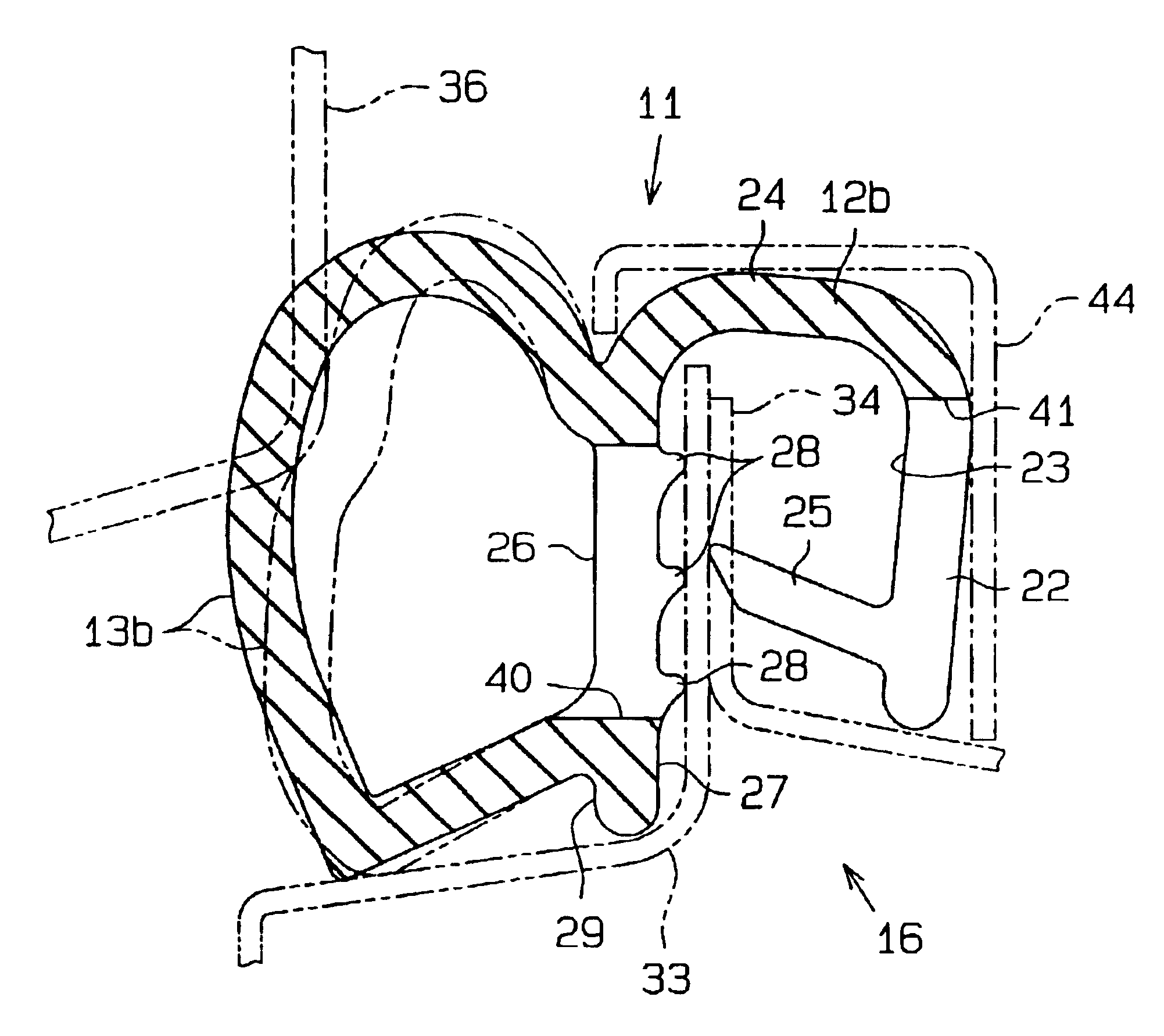
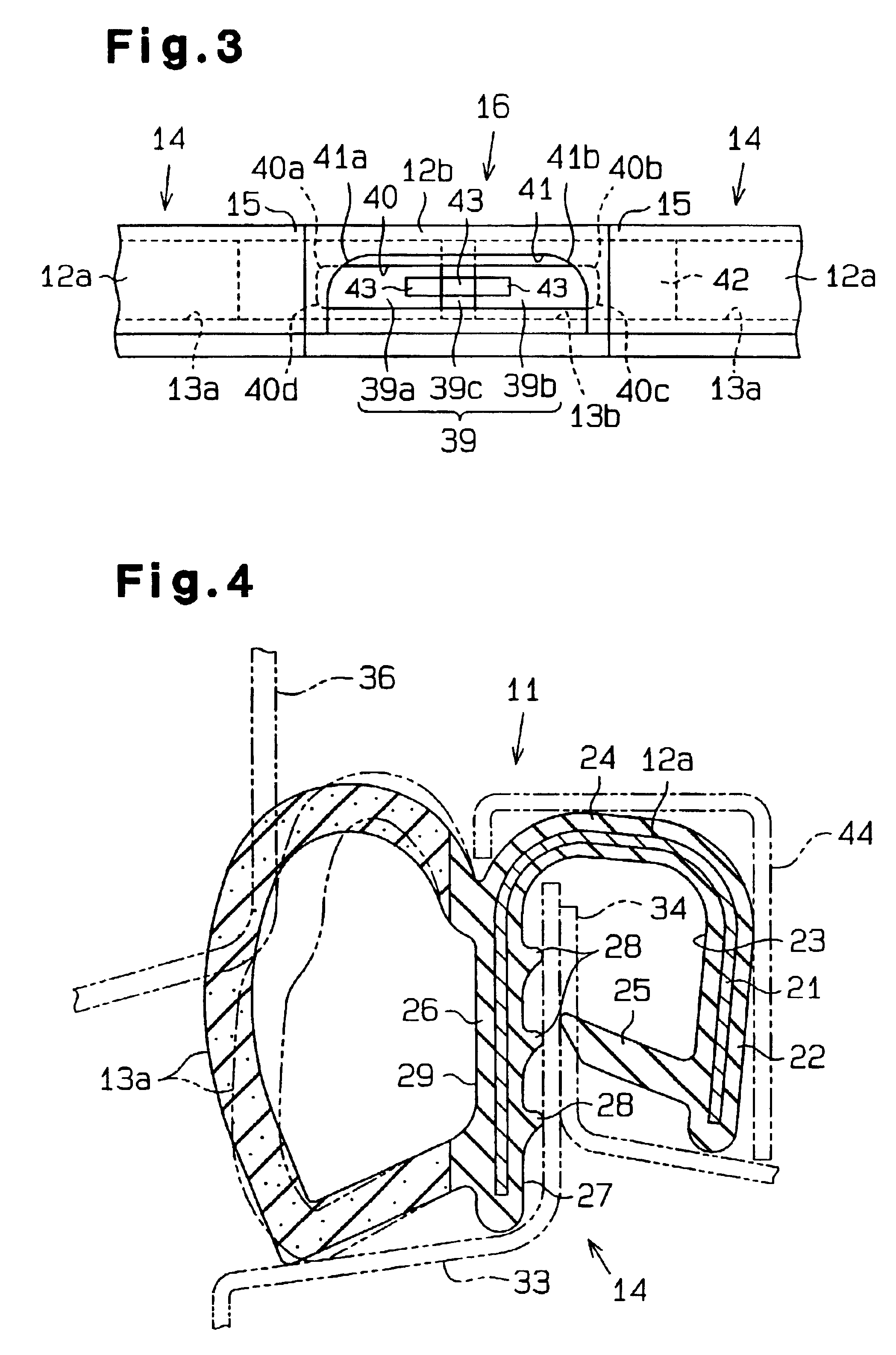
(1) In the weather strip 11, the slot 40, which is used to remove the core 39 from the hollow seal 13b after the molded portion 16 is molded, is located on the trim 12b of the molded portion 16. Since the hollow seals 13a, 13b do not have the slot 40, the rigidity of the hollow seal 13b in the molded portion 16 remains unchanged. Accordingly, the sealing capacity of the hollow seals 13a, 13b near the slot 40 is prevented from decreasing.

Further, the slot 40 is not visible from the hollow seal 13b. In addition, the hollow seal 13b does not deform when the weather strip 11 is attached to the flange 34 of the door opening 32. Thus, the weather strip 11 is not undulated when attached to the vehicle body. This maintains the appearance of the weather strip 11 in a satisfactory state.

(2) In the weather strip 11, the slot 40, which is used to remove the core 39, is formed in the outer side wall 26 of the U-shaped trim 12b in the molded...

second embodiment

The second embodiment has the advantages described below.

(1) In the weather strip 51, the slot 59 is provided in the trim 54 of the molded portion 52. The slot 59 is used when removing the core 58, which is used to mold the hollow seal 55 of the molded portion 52 that is located at the end of the weather strip 51, from the molded portion 52 subsequent to molding.

Thus, the slot 59 for removing the core 58 is not provided in the hollow seal 13a of the extruded portion 14 or the hollow seal 55 of the molded portion 52. Accordingly, the sealing capability of the hollow seals 13a, 55 is not decreased.

Further, the slot 59 for removing the core 58 is not visible from the hollow seals 13b, 55. In addition, the hollow seals 13b, 55 are not distorted when the weather strip 51 is attached to the flange 34 of the door opening 32. Therefore, undulating of the hollow seals 13b, 55 does not occur. This maintains satisfactory appearance of the weather strip 51 when the weather strip 51 is attached ...


PUM

PropertyMeasurementUnit
rigidityaaaaaaaaaa
flexibleaaaaaaaaaa
forceaaaaaaaaaa

Abstract

A weather strip having a high sealing capability and an aesthetic appearance when attached to a vehicle body. The weather strip includes an extruded portion and a molded portion connected to the extruded portion and having a trim and a hollow seal. The trim includes a first wall from which the hollow seal extends. The first wall has a slot provided with a rounded corner. A second wall extends from the first wall in a direction opposite the hollow seal. A third wall extends from the second wall in a manner opposing the first wall. The third wall includes a cutaway portion defined at a position facing the slot of the first wall. The cutaway portion includes a rounded corner. A core used to mold the hollow seal of the molded portion is removed from the molded portion through the slot and the cutaway portion.

Description

CROSS-REFERENCE TO RELATED APPLICATIONSThis application is related to and claims priority from Japanese Patent Application Nos. 2001-165422 and 2001-358202, the contents of which are incorporated herein by reference.BACKGROUND OF THE INVENTION1. Field of the InventionThe present invention relates to a weather strip, which is attached to a vehicle body around an opening that is opened and closed by a door, such as an opening trim weather strip.2. Description of Related ArtsA weather strip used for a vehicle includes a generally U-shaped trim and a hollow seal, which extends from a side wall or a bridging wall of the trim. Such a weather strip is required to seal gaps between the vehicle body and the door when the door is closed. In other words, such a weather strip must be airtight and waterproof when the door is closed.To form the weather strip, extrusion molding is performed to manufacture an elongated, extruded portion. The elongated portion is then bent in a looped manner so that...

Claims


Application Information

Patent Timeline
Patent Type & Authority Patents(United States)
IPC IPC(8): B29C45/14B60J10/00B60J10/08B60R13/06B29C45/26B29L24/00B29L31/30
CPCB29C45/14409B60J10/0005B60J10/08B60J10/0031B60J10/0065B60J10/0022B29L2031/26B60J10/24B60J10/2335B60J10/16B60J10/32B60J10/80
Inventor NOZAKI, MASAHIROKUBO, YOSHIHISAINOUE, TOMONORI
Owner TOYODA GOSEI CO LTD
Why Eureka
Try Eureka