
Method and apparatus for adjusting the temperature set point based on humidity level for increased comfort

Active Publication Date: 2005-01-18
HONEYWELL INT INC
View PDF10 Cites 43 Cited by
  • Summary
  • Abstract
  • Description
  • Claims
  • Application Information

AI Technical Summary

Benefits of technology

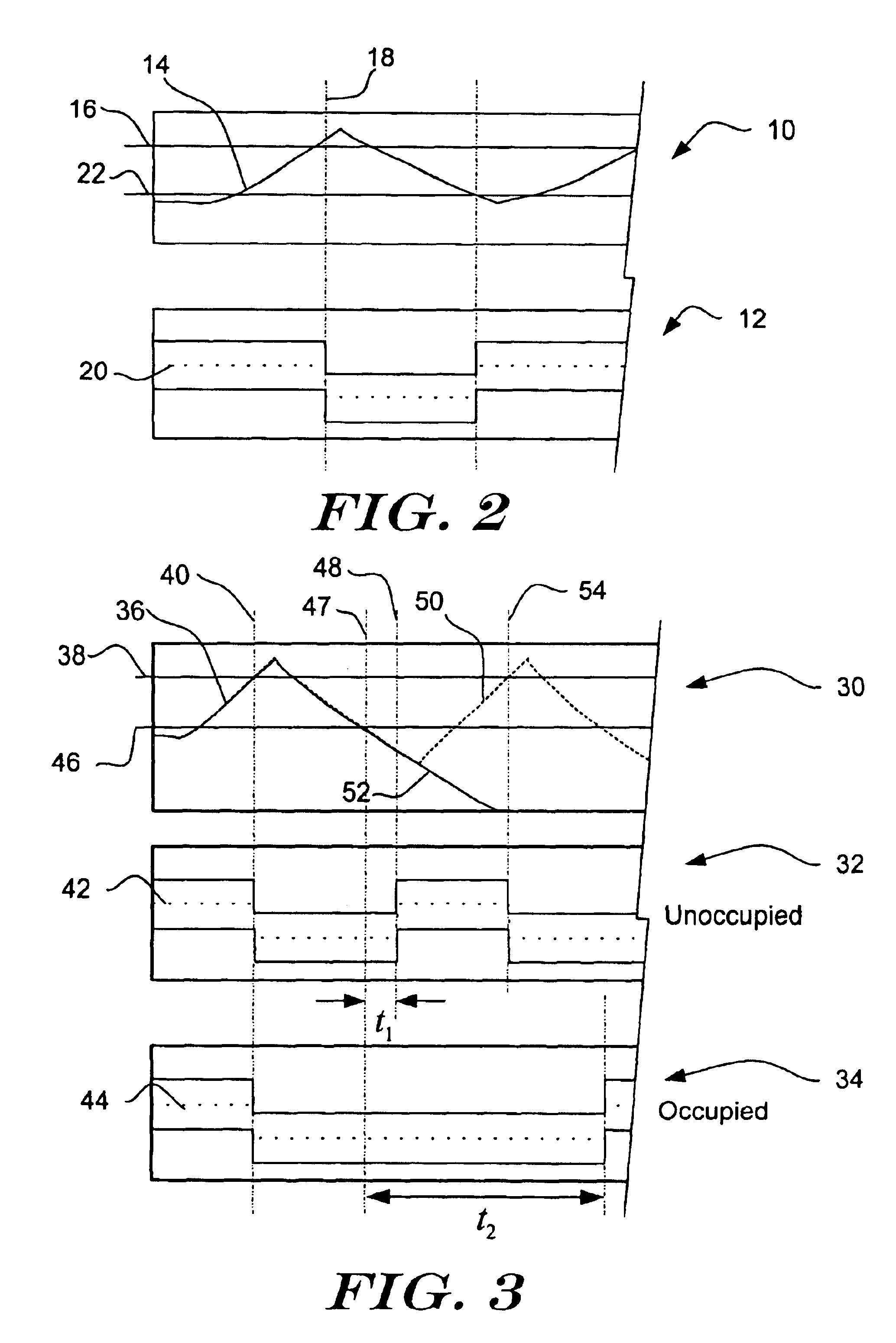
When the space is expected to be unoccupied, and occupant comfort is less of a concern, the temperature set point may be allowed to return to the previous higher set point value after a relatively short time period. A relatively short time period can be used because relatively short term temperature cycling in the inside space is less of a concern when no occupants are present, and maintaining a lower temperature set point value for a longer time period may consume additional energy. When the space is occupied, however, and occupant comfort is more of a concern, the temperature set point may remain at the new lower temperature set point for a longer period of time. The longer predetermined time period may help reduce relatively short term temperature cycling in the inside space, which under some circumstances, may be noticeable and somewhat uncomfortable for occupants in the inside space. In addition, the use of a lower temperature set point during periods of high humidity may create better perceived comfort for occupants. In some embodiments, the humidity level may correspond to a relative humidity level. However, any suitable measure of humidity may be used, as desired.

Problems solved by technology

A relatively short time period can be used because relatively short term temperature cycling in the inside space is less of a concern when no occupants are present, and maintaining a lower temperature set point value for a longer time period may consume additional energy.
The longer predetermined time period may help reduce relatively short term temperature cycling in the inside space, which under some circumstances, may be noticeable and somewhat uncomfortable for occupants in the inside space.

Method used


Image

  • Method and apparatus for adjusting the temperature set point based on humidity level for increased comfort
  • Method and apparatus for adjusting the temperature set point based on humidity level for increased comfort
  • Method and apparatus for adjusting the temperature set point based on humidity level for increased comfort

Examples


Embodiment Construction

The following detailed description should be read with reference to the drawings. The drawings, which are not necessarily to scale, depict illustrative embodiments and are not intended to limit the scope of the invention.

The present invention creates conditions within an inside space which are more comfortable for occupants by reducing the set point temperature when humidity is high. In addition, by reducing the temperature when the humidity is high, the supporting air conditioner may run for longer periods of time to maintain the reduced temperature set point, which can remove additional water from the inside space.

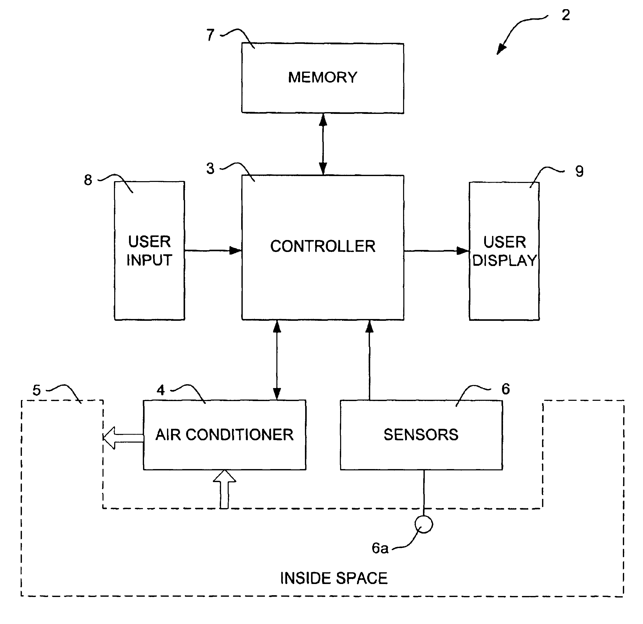
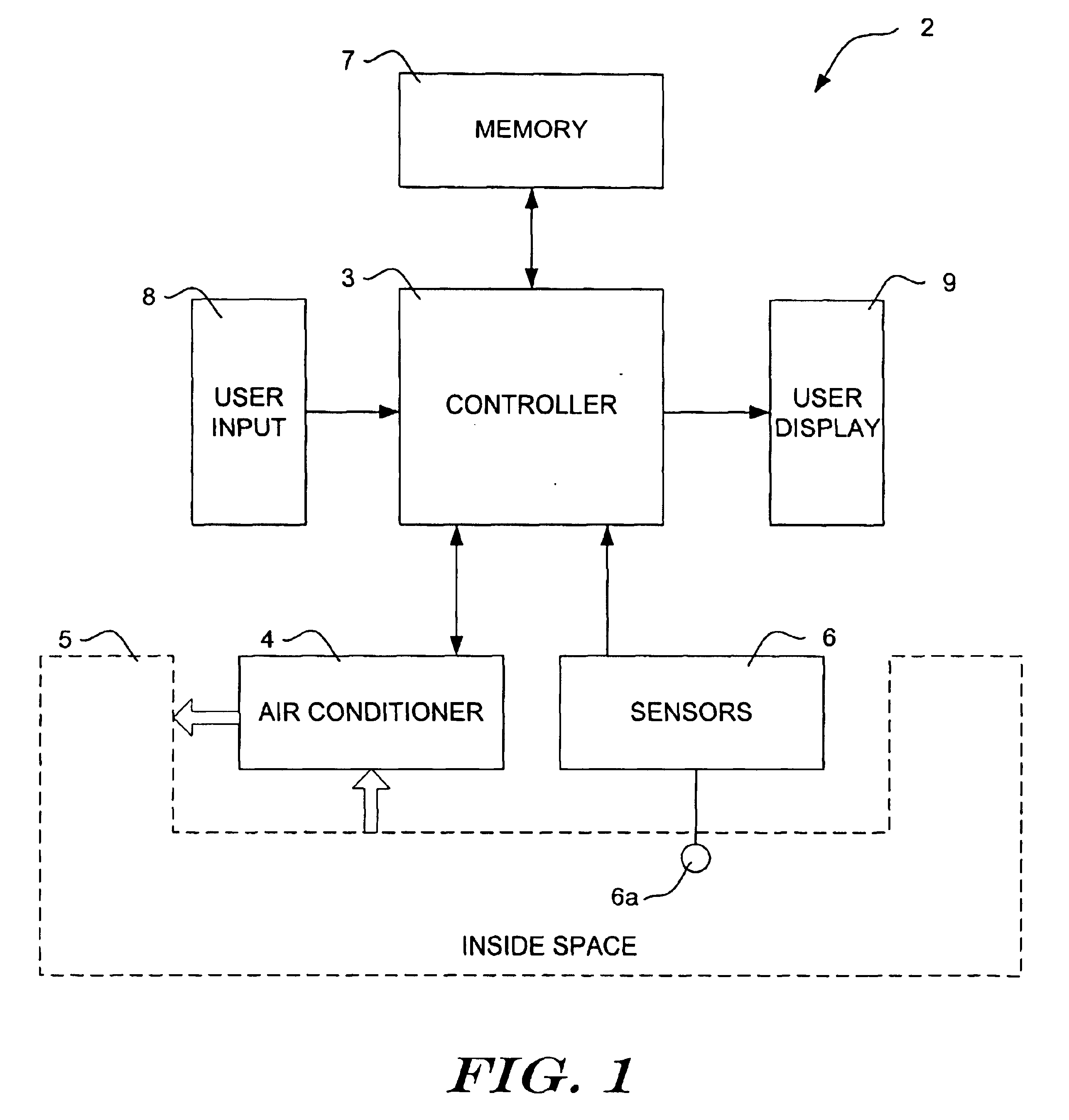
FIG. 1 is a block diagram of an illustrative system for controlling an air conditioner in accordance with the present invention. The system is generally shown at 2, and includes a controller 3 for controlling an air conditioner4 that is adapted to service an inside space 5. The controller 3 is preferably a microprocessor that is controlled by software stored in memory 7....


PUM


Abstract

Methods and apparatus for using humidity level to adjust the temperature set point of an HVAC system for increased occupant comfort. In one illustrative embodiment, the temperature set point for the inside space is moved downward when the humidity of the inside space rises above a predetermined humidity set point threshold value. In warm climates, this causes the air conditioner of the HVAC system to be activated, which lowers the temperature of the inside space to a new lower temperature set point. In some embodiments, the HVAC system retains the new lower temperature set point for a predetermined time period. The predetermined time period may be dependent on a number of factors, including whether the space is expected to occupied or unoccupied.

Description

The present invention generally relates to the field of heating, ventilation, and air conditioning (HVAC), and more particularly to temperature set point control based on humidity for increased comfort.BACKGROUNDHVAC systems are commonly used to control the temperature of the inside space of a building or other structure. Many HVAC systems do not attempt to control humidity, even though humidity can play a significant role in occupant comfort. For many residential and commercial HVAC systems, humidity is reduced as merely a byproduct of operating the cooling system. While HVAC systems have long been adapted to use temperature as the standard for determining when to provide heating or cooling, new strategies are needed to incorporate humidity effects on perceived comfort.SUMMARYThe present invention provides methods and apparatus for using humidity level to adjust the temperature set point of an HVAC system for increased occupant comfort. In one illustrative embodiment, the temperatu...

Claims


Application Information

Patent Timeline
IPC IPC(8): F24F11/00
CPCF24F11/0015F24F11/30F24F2110/20F24F11/65
Inventor WACKER, PAUL C.
Owner HONEYWELL INT INC
Learn More