
Screen unit and display system

a display system and screen technology, applied in the field of screen units and display systems, can solve the problems of complex inconvenient adjustment of video projectors, and inability to maintain the same size screen, and achieve the effect of easy adjustment of the outline of images

Inactive Publication Date: 2005-01-18
MITSUBISHI ELECTRIC CORP +1
View PDF12 Cites 6 Cited by
  • Summary
  • Abstract
  • Description
  • Claims
  • Application Information

AI Technical Summary

Benefits of technology

It is therefore a first object of the invention to provide a screen unit with flatness not impaired by the temperature difference. It is a second object of the invention to provide a screen unit for making it possible to easily adjust the outline of an image. It is a third object of the invention to provide a display system for projecting an image fitted to viewing of observers.
The semipermeable screen sheet can be prevented from being bent due to a temperature, an image occupying the full semipermeable screen sheet can be projected easily, and the visual effect as if the image floated in the air is provided.
If the observer moves to the front and the back of the screen unit, he or she can observe the normal image and more effective display is made possible from the viewpoint of business.
Black floating, which means that outside light causes the black portion to become whitish for degrading the image contrast, is decreased and the contrast is improved to about twice.

Problems solved by technology

The semipermeable screen is thin and has no mechanical strength.
Thus, it has been intricate to adjust the video projector to match the image and the frame of the screen unit.
Since the frame touches the screen sheet, adjustment for matching the image with the frame is intricate.
Further, in the display system in the related art as described above, when the observer facing one display face of the screen unit simultaneously displaying a reflected image and a transmitted image goes round to the back, the front and the back of the image are reversed; this is a problem.

Method used


Image

  • Screen unit and display system
  • Screen unit and display system
  • Screen unit and display system

Examples


first embodiment

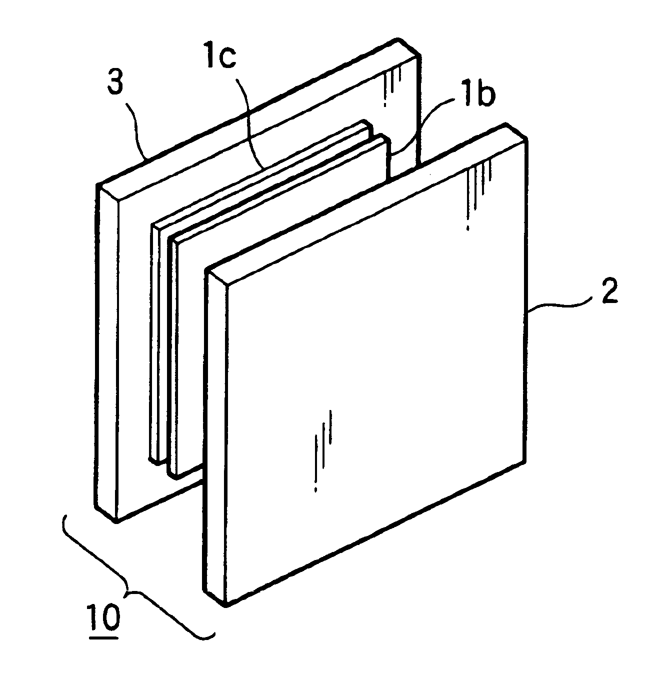
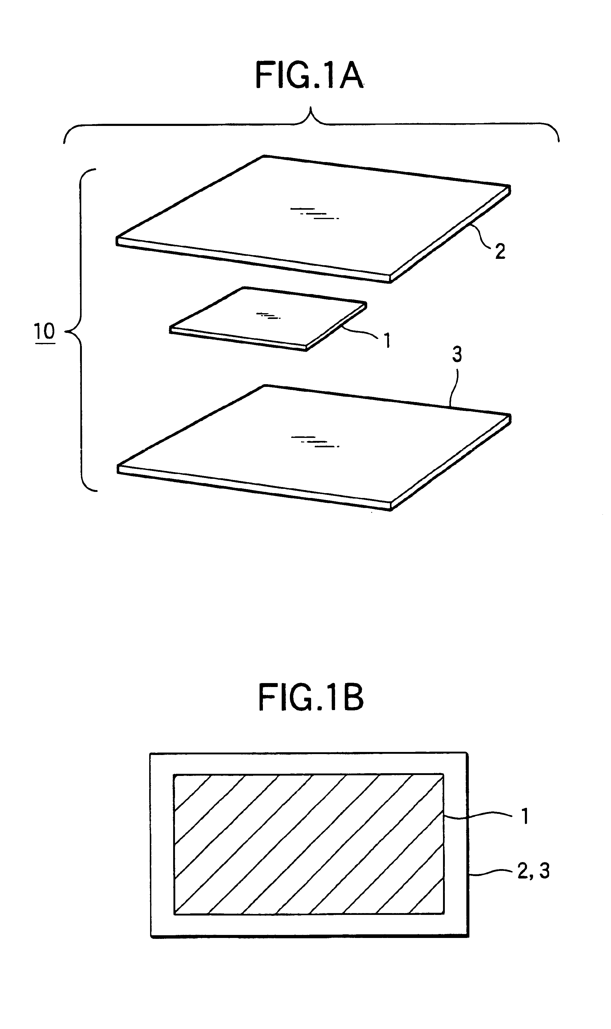
FIG. 1A is a drawing to represent configuration of a screen unit according to a first embodiment of the invention. In FIG. 1A, numeral 1 denotes a semipermeable screen sheet for transmitting and reflecting a projected image in a constant percentage (for example, transmitting light 60% and reflecting 40%), numeral 2 denotes a first transparent sheet such as an acrylic sheet wider than the semipermeable screen sheet 1, numeral 3 denotes a second transparent sheet which is the same as the first transparent sheet 2, and numeral 10 denotes a screen unit including the semipermeable screen sheet 1 sandwiched between the first transparent sheet 2 and the second transparent sheet 3. According to the configuration, the semipermeable screen sheet 1 can be fixed to a plane and is reinforced with the first transparent sheet 2 and the second transparent sheet 3, so that deformation of warpage or distortion of the screen unit 10 caused by the temperature difference is hard to occur.

FIG. 1B is a fr...

second embodiment

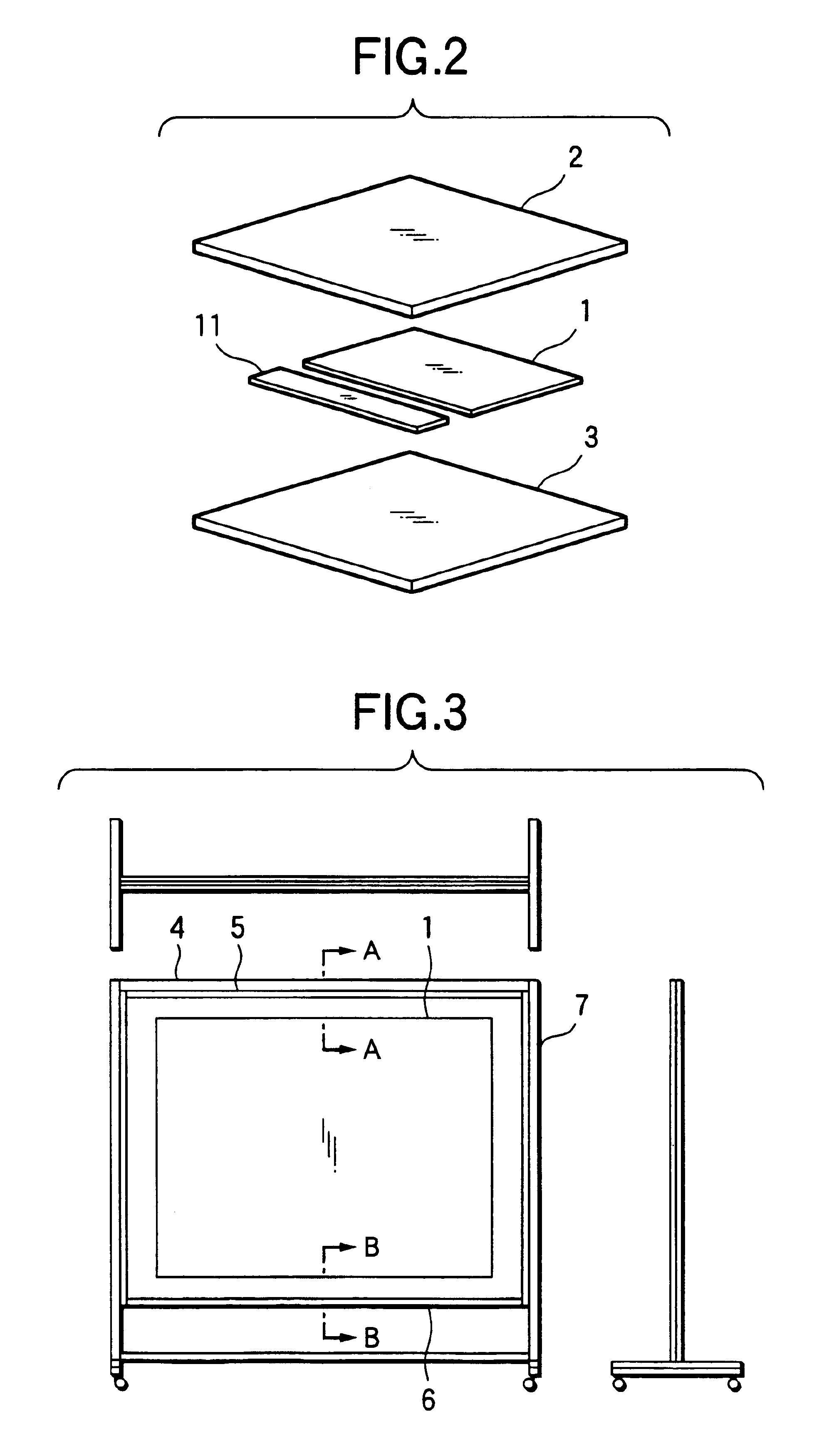
FIG. 2 is a developed view of a screen unit according to a second embodiment of the invention. In FIG. 2, numeral 11 denotes a liquid crystal display sheet sandwiched between a first transparent sheet 2 and a second transparent sheet 3. According to the configuration, when a projected image is displayed on a semipermeable screen sheet 1, another information is displayed on the liquid crystal display sheet 11 in continuous-flow text, etc. Since multiple pieces of information can be provided at the same time and the information projected onto the semipermeable screen sheet 1 easily depends on the external environment of outside light, etc., only important information is displayed directly on the liquid crystal display sheet 11, thereby improving the information conveyance capability.

third embodiment

FIG. 3 is a three-view drawing of a screen unit attached to a cabinet according to a third embodiment of the invention. In FIG. 3, numeral 4 denotes a seal member for filling in surrounding gaps of a semipermeable screen sheet 1 produced when the semipermeable screen sheet 1 is sandwiched between a first transparent sheet 2 and a second transparent sheet 3. Numeral 5 denotes an upper screen frame for fixing the upper portion of the semipermeable screen sheet 1 with the first transparent sheet 2 and the second transparent sheet 3. Numeral6 denotes a surrounding screen frame for holding the semipermeable screen sheet 1 without applying any force to the first transparent sheet 2, the second transparent sheet 3, or the seal member 4. Numeral 7 denotes a cabinet frame with a moving caster for holding the upper screen frame 5 and the surrounding screen frame 6, thereby holding a screen unit 10.

Since only the upper portion of the semipermeable screen sheet 1 is fixed, if a temperature diff...


PUM


Abstract

A screen unit includes a semipermeable screen sheet sandwiched between a first transparent sheet and a second transparent sheet. The semipermeable screen sheet transmits and reflects a projected image in a constant percentage. The first transparent sheet such as an acrylic sheet wider than the semipermeable screen sheet. The second transparent sheet is the same as the first transparent sheet.

Description

BACKGROUND OF THE INVENTION1. Field of the InventionThis invention relates to a screen unit and a display system in an image projection display.2. Description of the Related ArtHitherto, a projected image from a video projector has been projected onto a screen unit and has been reflected or transmitted, whereby the observer has viewed the image. In the screen unit, the semipermeable screen sheet itself has predetermined reflectivity and transmissivity. The semipermeable screen is thin and has no mechanical strength. Thus, the semipermeable screen has been bonded fully onto a transparent reinforcing sheet and has been covered in surroundings with a frame for use. Thus, it has been intricate to adjust the video projector to match the image and the frame of the screen unit.In the screen unit in the related art as described above, the screen sheet providing the image projection face is easily bent because of the thermal expansion coefficient difference between the screen sheet and the r...

Claims


Application Information

Patent Timeline
Patent Type & Authority Patents(United States)
IPC IPC(8): G03B21/62G03B21/60
CPCG03B21/625
Inventor TERAMOTO, KOHEISATO, YASUOSAKAKIBARA, YOSHINORI
Owner MITSUBISHI ELECTRIC CORP
Learn More