Radio communication system and radio terminal device using faster and slower radio networks cooperatively

a radio communication system and radio terminal technology, applied in the field of radio communication system and radio terminal device using faster and slower radio networks cooperatively, can solve the problems of reducing the price of these radio lan products, implementing a radio network to the home environment, and wideband data transfer using radio

Inactive Publication Date: 2005-01-18
KK TOSHIBA
View PDF6 Cites 80 Cited by
  • Summary
  • Abstract
  • Description
  • Claims
  • Application Information

AI Technical Summary

Benefits of technology

It is therefore an object of the present invention to provide a communication system and a terminal device using first and second networks, where the terminal device can receive data transfers as a receiving node in the first network, even when the terminal device has a first network interface through which only reception is possible and a second network interface through which both transmission and reception are possible.

Problems solved by technology

In particular, since the determination of the IEEE 802.11 specification in 1998, many radio LAN products are appearing in the market and there has been a remarkable decrease in the prices of these radio LAN products.
However, there are some outstanding problems in the application of a radio network to the home environment.
One such problem is the realization of a wideband data transfer using radio.
But the 5 GHz band radio system also has its own problems.
Namely, it is currently impossible to realize LSI of the RF function using CMOS.
This is a severe drawback in view of a low cost realization of the 5 GHz radio system, and its resolution is imperative since it is expected that wider spread of radio systems in the home environment critically depends on how cheaply this 5 GHz band radio system can be offered to the general users.
As described, a radio device for transferring wideband data such as 5 GHz band radio system is expected to be rather expensive, and for this reason it is expected that a cost of the radio terminal itself will be very high in realizing the video data delivery in the home environment.
This is a very serious problem for very cost sensitive products such as home electronic devices.

Method used


Image

  • Radio communication system and radio terminal device using faster and slower radio networks cooperatively
  • Radio communication system and radio terminal device using faster and slower radio networks cooperatively
  • Radio communication system and radio terminal device using faster and slower radio networks cooperatively

Examples


first embodiment

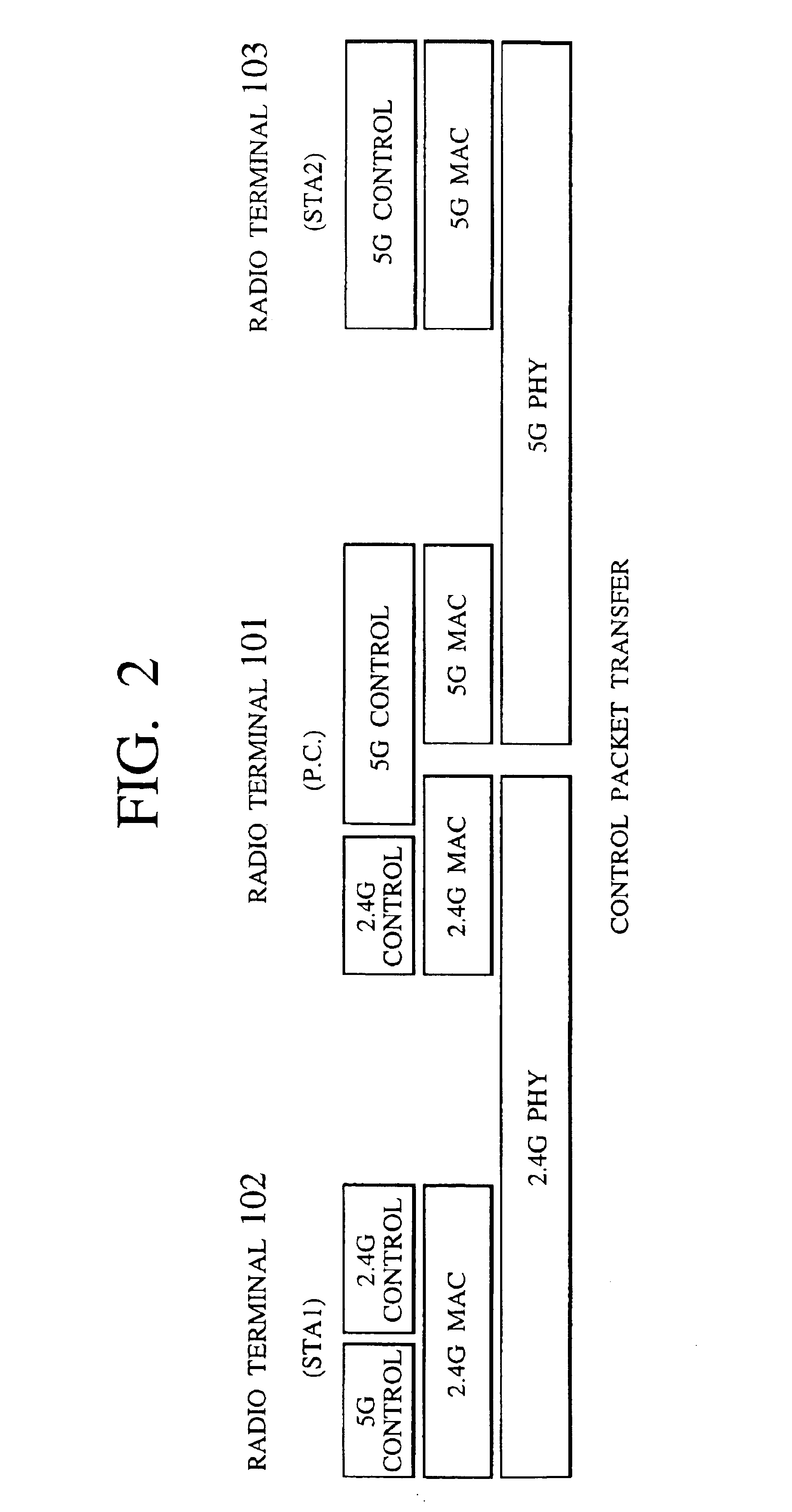
This first embodiment is directed to a scheme by which a radio terminal having only a reception function with respect to the 5 GHz band radio LAN (or capable of utilizing only a reception function with respect to the 5 GHz band radio LAN) carries out a processing (such as authentication / admission processing, for example) with respect to the 5 GHz band radio LAN, via the 2.4 GHz band radio LAN.

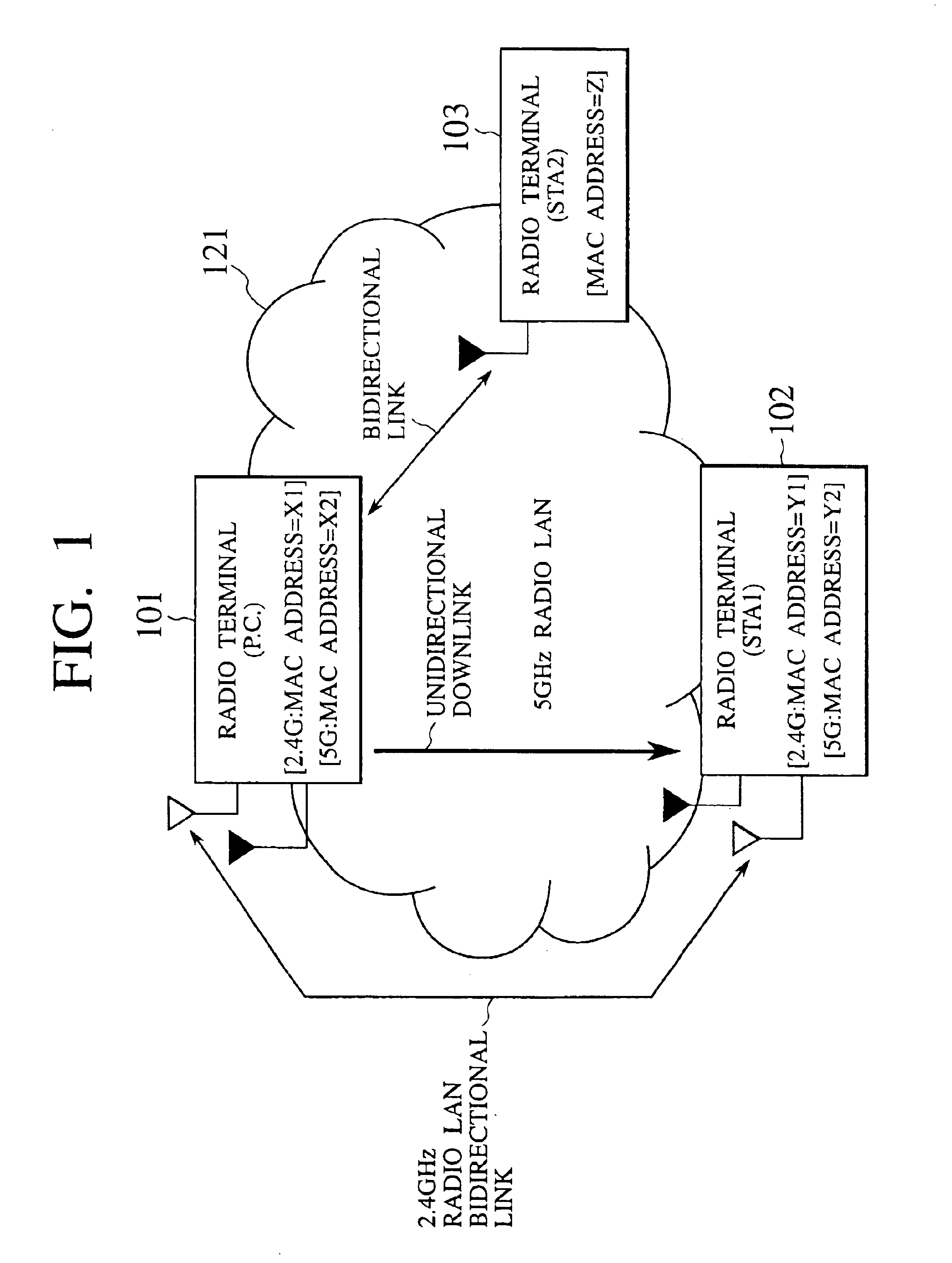
FIG. 1 shows an exemplary configuration of a network system in which the 5 GHz band radio LAN and the 2.4 GHz band radio LAN are used cooperatively. These radio LANs are both operated according to the IEEE 802.11 protocol, but uses different radio frequencies so that there is no interference between them.

The network system of FIG. 1 includes a radio terminal 101 which provides a P.C. (Point Coordinator) function in the 5 GHz band radio LAN 121, a radio terminal 103 which has transmission and reception functions with respect to the 5 GHz band radio LAN, and a radio terminal 102 which has only a ...

second embodiment

Referring now to FIG. 8 to FIG. 10, a radio communication system and a radio terminal device according to the present invention will be described in detail.

In the first embodiment, the data transfer from the radio terminal 101 which is the P.C. to the radio terminal 102 has been described. In this second embodiment, the data transfer from the radio terminal 103 to the radio terminal 102 (in a configuration basically similar to that of the first embodiment) will be described. Also, in this second embodiment, the case of the data transfer from the radio terminal 103 to the radio terminal 102 using the ordinary MAC processing (by the radio terminal 103) and the case of the data transfer from the radio terminal 103 to the radio terminal 102 relayed by the radio terminal 101 which is the P.C. will be described.

FIG. 8 shows a configuration similar to that of the first embodiment, in which the data transfer from the radio terminal 103 to the radio terminal 102 is realized. In this example,...

third embodiment

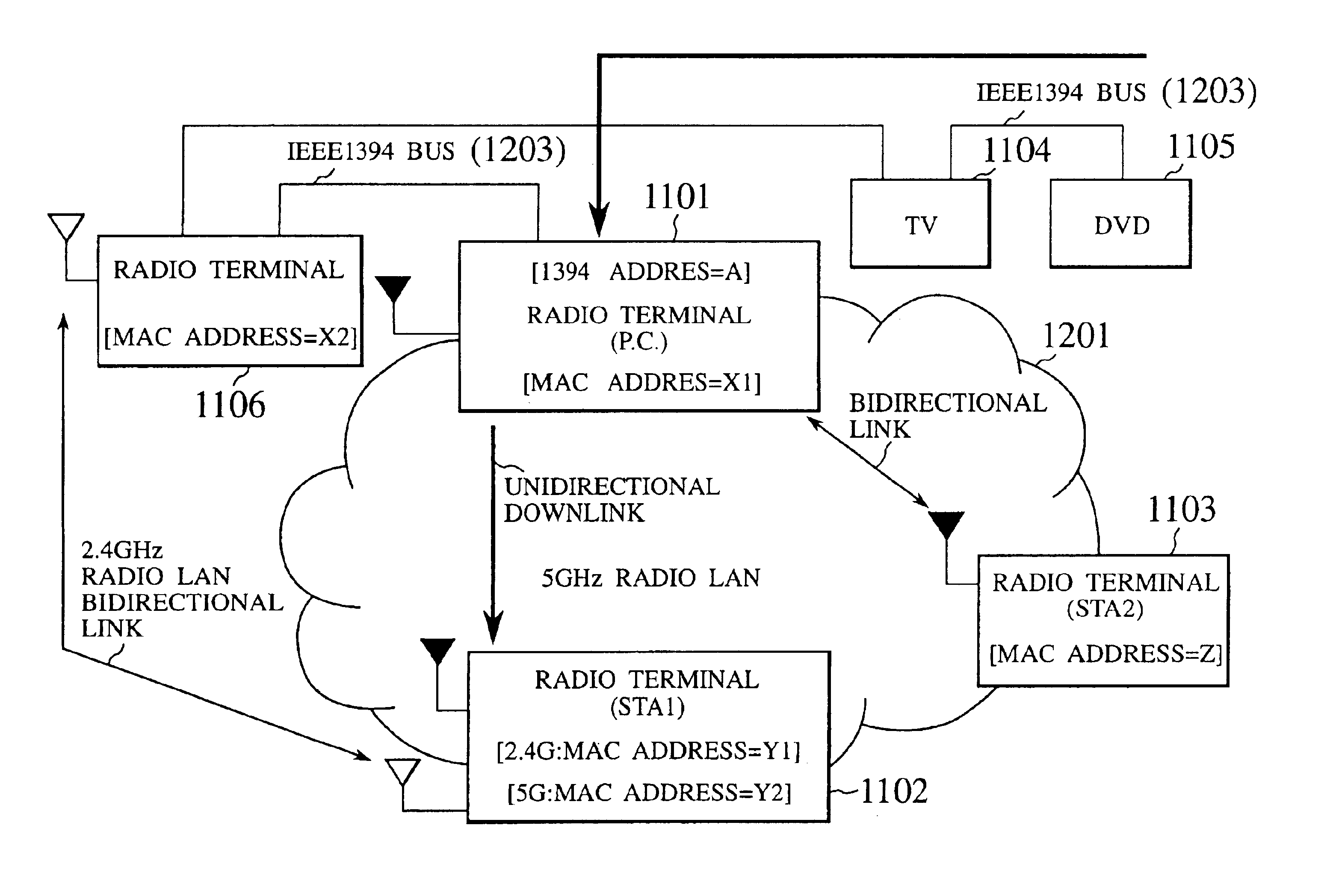
This third embodiment is directed to the case of operating the radio network (using the 2.4 GHz band radio LAN and the 5 GHz band radio LAN) together with the IEEE 1394 bus.

In this embodiment, a radio terminal having a P.C. function which is capable of carrying out communications by both the 2.4 GHz band radio LAN and the 5 GHz band radio LAN is provided on the IEEE 1394 bus, and this radio terminal relays the data transfer to the radio terminal which has (or which is capable of utilizing) only a reception function with respect to the 5 GHz band radio LAN from a device on the IEEE 1394 bus such as a DVD.

The example described here is directed to the case where the radio terminal on the radio network downloads image information from a DVD existing on the IEEE 1394 bus, and in particular the AV control protocol is executed between this radio terminal and the DVD via the 2.4 GHz band radio LAN, and the actual image data are received via the 5 GHz band radio LAN.

FIG. 11 shows an exemplar...


PUM


Abstract

A communication system including a first terminal device connected to first and second networks, having only a reception function with respect to the first network and transmission and reception functions with respect to the second network, the first network being a radio network according to IEEE 802.11 and the second network being a radio network slower than the first network, and a second terminal device connected to the first and second networks, having at least a transmission function with respect to the first network and transmission and reception functions with respect to the second network is disclosed. In this communication system, the first terminal device carries out a prescribed procedure required in using the first terminal as a receiving side in the first network, by carrying out communications with the second terminal device through the second network, the second terminal device transmits a prescribed information to the first network on behalf of the first terminal device, the prescribed information being an information required to be transmitted to the first network in order for the first terminal device to receive packets through the first network, and the first terminal device receives the packets through the first network.

Description

BACKGROUND OF THE INVENTION1. Field of the InventionThe present invention relates to a radio terminal device (which is also referred to as a wireless terminal device) having a plurality of communication interfaces and a radio communication system (which is also referred to as a wireless communication system) including such radio terminal devices.2. Description of the Background ArtIn recent years, the realization of home network is attracting much attention, and in particular, the IEEE 1394 for connecting between digital home electronic devices has been attracting considerable attention. The IEEE 1394 bus is capable of connecting a plurality of terminals in daisy chain or star connection and transferring a wideband data in excess of 100 Mbps. Also, it has a major feature that it is possible to transmit both asynchronous data and isochronous data on the same cable. For this reason, even though the IEEE 1394 bus was originally developed as a next generation version of SCSI, there are ...

Claims


Application Information

Patent Timeline
Patent Type & Authority Patents(United States)
IPC IPC(8): H04L12/56H04L12/28H04L29/06H04B7/26H04L12/40H04L12/46H04W4/00H04W28/00H04W28/22H04W72/04H04W84/12H04W88/02H04W88/06
CPCH04W28/22H04L12/5692H04W92/02H04W88/02H04W88/04H04W12/06H04W84/12H04W88/06
Inventor TAKABATAKE, YOSHIAKITOSHIMITSU, KIYOSHITAMADA, YUZO
Owner KK TOSHIBA
Why Eureka
Try Eureka