Rotatable cutting tool

a cutting tool and rotating technology, applied in the field of cutting tools, can solve the problems of requiring couplings, requiring sliding seals between internal pistons and cavities containing hydraulic fluids, and affecting the operation of adjusting devices,

Inactive Publication Date: 2005-01-25
VALENITE
View PDF11 Cites 32 Cited by
  • Summary
  • Abstract
  • Description
  • Claims
  • Application Information

AI Technical Summary

Benefits of technology

In accordance with the aforesaid objects the present invention provides a rotatable cutting tool having a shank portion for mounting to a tool driving device and a cutting portion to which is attached at least one support member for retention of a replaceable cutting element. The support member is so arranged to permit displacement of at least the portion thereof retaining the cutting element whereb

Problems solved by technology

Tools of this type have the inherent disadvantage of requiring couplings for supply of hydraulic fluid through the tool driving device.
Such known tools have the disadvantage of requiring sliding seals between

Method used


Image

  • Rotatable cutting tool
  • Rotatable cutting tool
  • Rotatable cutting tool

Examples


Embodiment Construction

The invention shall be described with reference to a preferred embodiment illustrated in the accompanying figures. While the preferred embodiment illustrates features of the invention, it is not the intention of applicants that the invention be limited to particular details of the preferred embodiment.

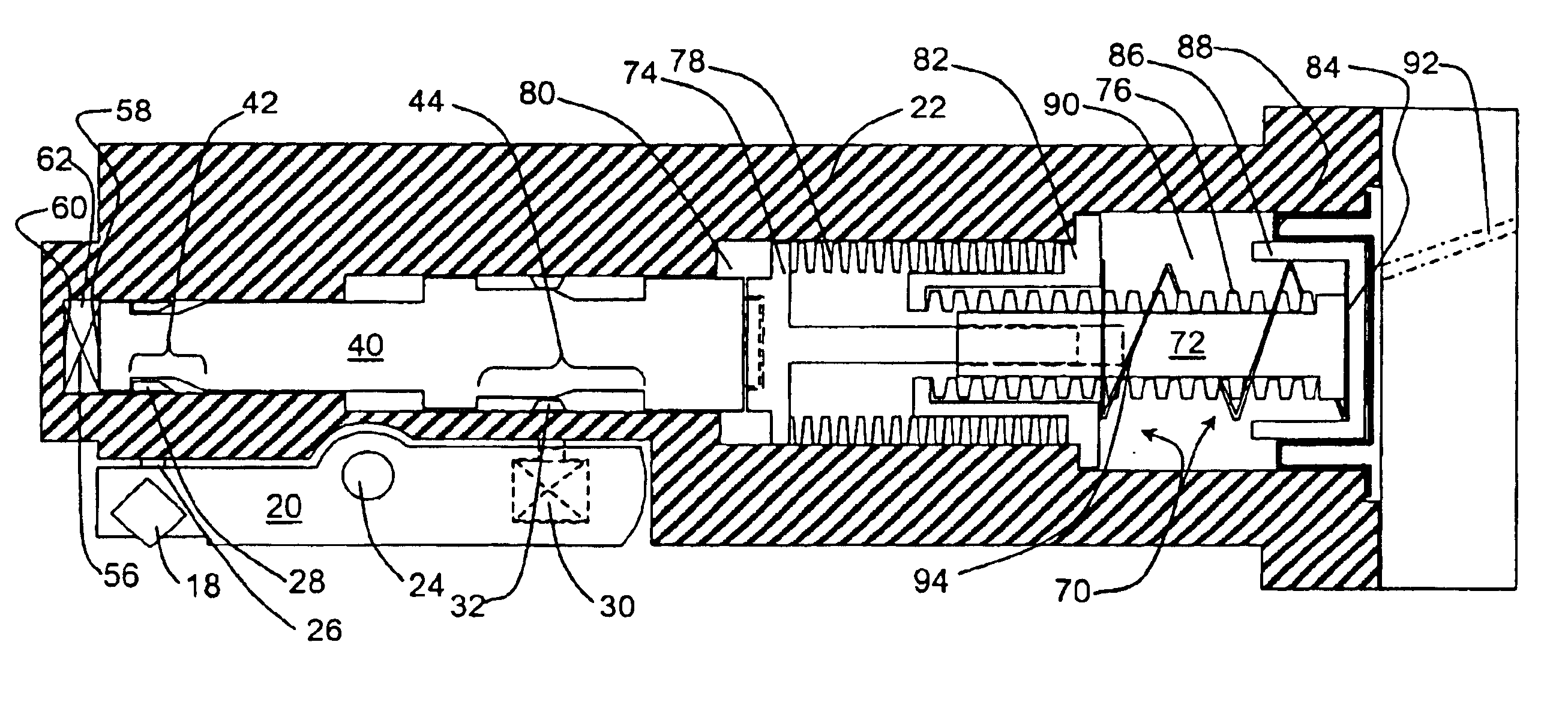
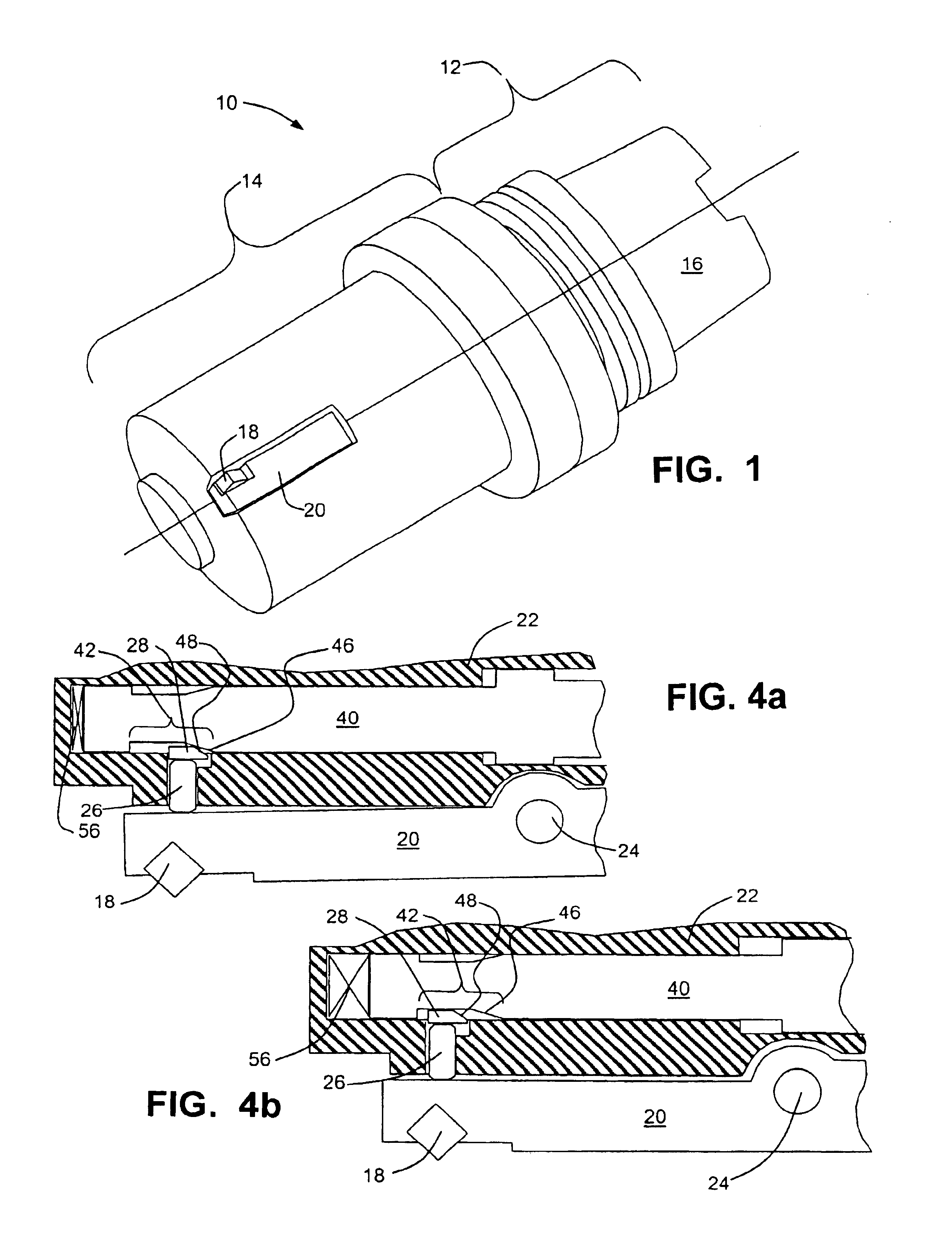
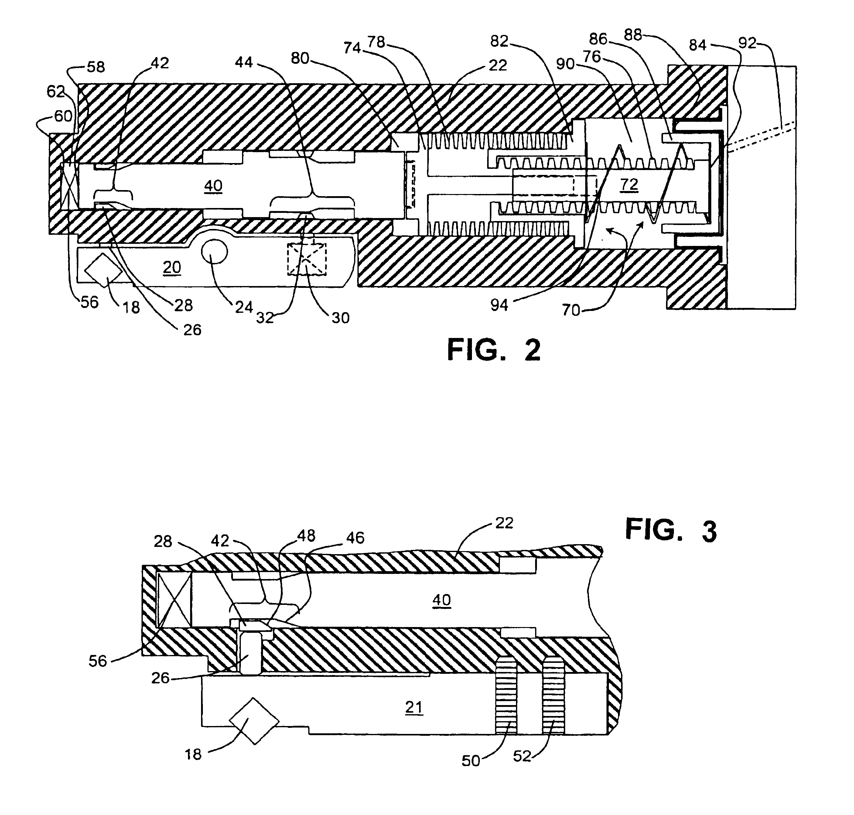
A rotatable cutting tool 10 depicted in FIG. 1 includes a shank portion 12 and a cutting portion 14. Shank portion 12 is suitable for mounting to an adapter 16 for connection to a tool driving apparatus such as the rotatable spindle of a machine. Adapter 16 may be suitable for tool driving spindles of machines lacking automatic tool changing mechanisms. Further, adapter 16 advantageously conforms to standards to assure compatibility with standardized automatic tool changing equipment, such as well known standards for such adapters: HSK; DIN ISO / DIS 12164-1 & -2; ANSI 7 / 24 tapers; and, Japan's BT 7 / 24 tapers. Cutting portion 14 is generally cylindrical and comprises a cutter body 22 to ...


PUM

PropertyMeasurementUnit
Forceaaaaaaaaaa
Pressureaaaaaaaaaa
Internal pressureaaaaaaaaaa

Abstract

A rotatable cutting tool has a shank portion for coupling to a tool driving device and a cutting portion to which is attached at least one support member for retention of a replaceable cutting element. The support member is so arranged to permit displacement of at least the portion thereof retaining the cutting element whereby the position of the cutting element relative to the body of the cutting tool may be changed by such displacement. A totally enclosed hydraulic force multiplier is mounted within an internal cavity of the cutting tool. The force multiplier is responsive to a control force to effect the displacement of the support member, the control force advantageously supplied by application of pneumatic pressure.

Description

BACKGROUND OF THE INVENTIONI. Field of the InventionThis invention relates to cutting tools and particularly to rotatable cutting tools of the type having at least one cutting element the position of which relative to the tool is adjustable by remotely controllable adjusting devices. More particularly, this invention relates to improved actuators for remotely controlled adjusting of relative position of cutting elements of rotatable cutting tools.II. Description of Related ArtKnown rotatable tools comprising position adjustable cutting elements use various means for effecting changes of position of the cutting elements. Examples of such rotatable tools using mechanical actuating devices are illustrated in EP Patent Application No. 1123766. An example of a rotatable tool using hydraulic actuating devices requiring supply of hydraulic fluid is illustrated in Japanese Utility Model Application No. 62-201231. Tools of this type have the inherent disadvantage of requiring couplings for s...

Claims


Application Information

Patent Timeline
IPC IPC(8): B23B29/00B23B29/034C12N15/38
CPCB23B29/03457B23B2270/025Y10T408/8583Y10T408/85843Y10T408/8588B23B2270/027B23B29/03B23B29/12B23B29/02
Inventor BROCK, JAMES R.ROBINSON, JAMES J.
Owner VALENITE
Why Eureka
Try Eureka