
Algebraic codebook system and method

a codebook and algebraic technology, applied in the field of electromechanical devices, can solve the problem that algebraic codebook vectors still require too many bits for encoding more than two pulses

Inactive Publication Date: 2005-01-25
TEXAS INSTR INC
View PDF6 Cites 33 Cited by
  • Summary
  • Abstract
  • Description
  • Claims
  • Application Information

AI Technical Summary

Benefits of technology

The present invention provides a way to encode and decode pulse position codes using the order of the codes within the codeword. This method requires fewer bits for coding, making it more efficient.

Problems solved by technology

However, the algebraic codebook vectors still require too many bits for encoding more than two pulses per track.

Method used


Image

  • Algebraic codebook system and method
  • Algebraic codebook system and method
  • Algebraic codebook system and method

Examples


Embodiment Construction

1. Overview

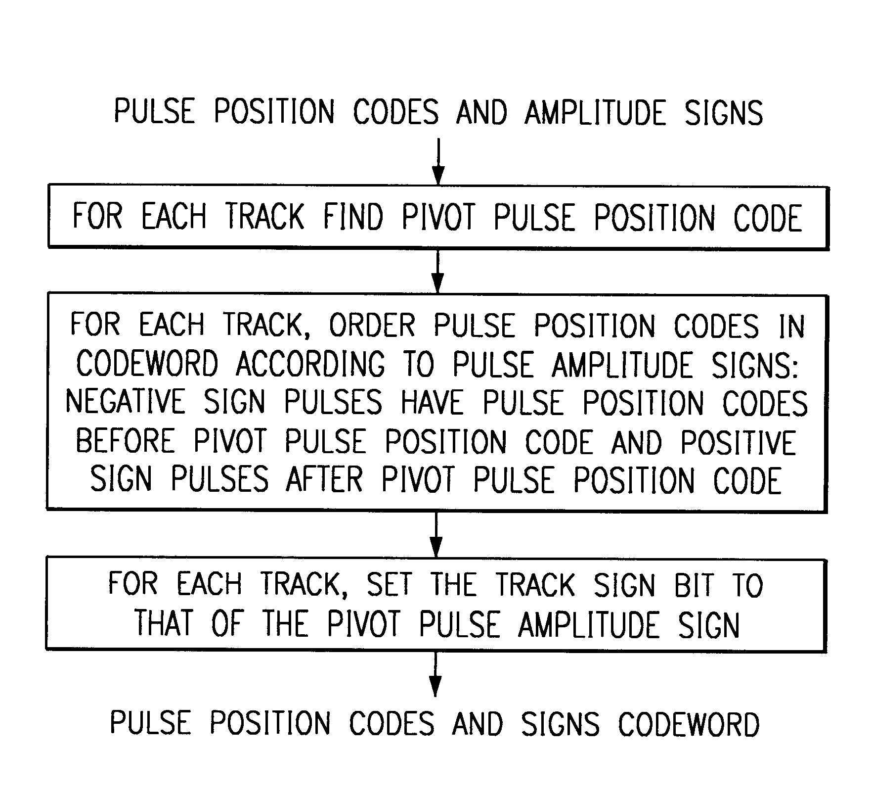
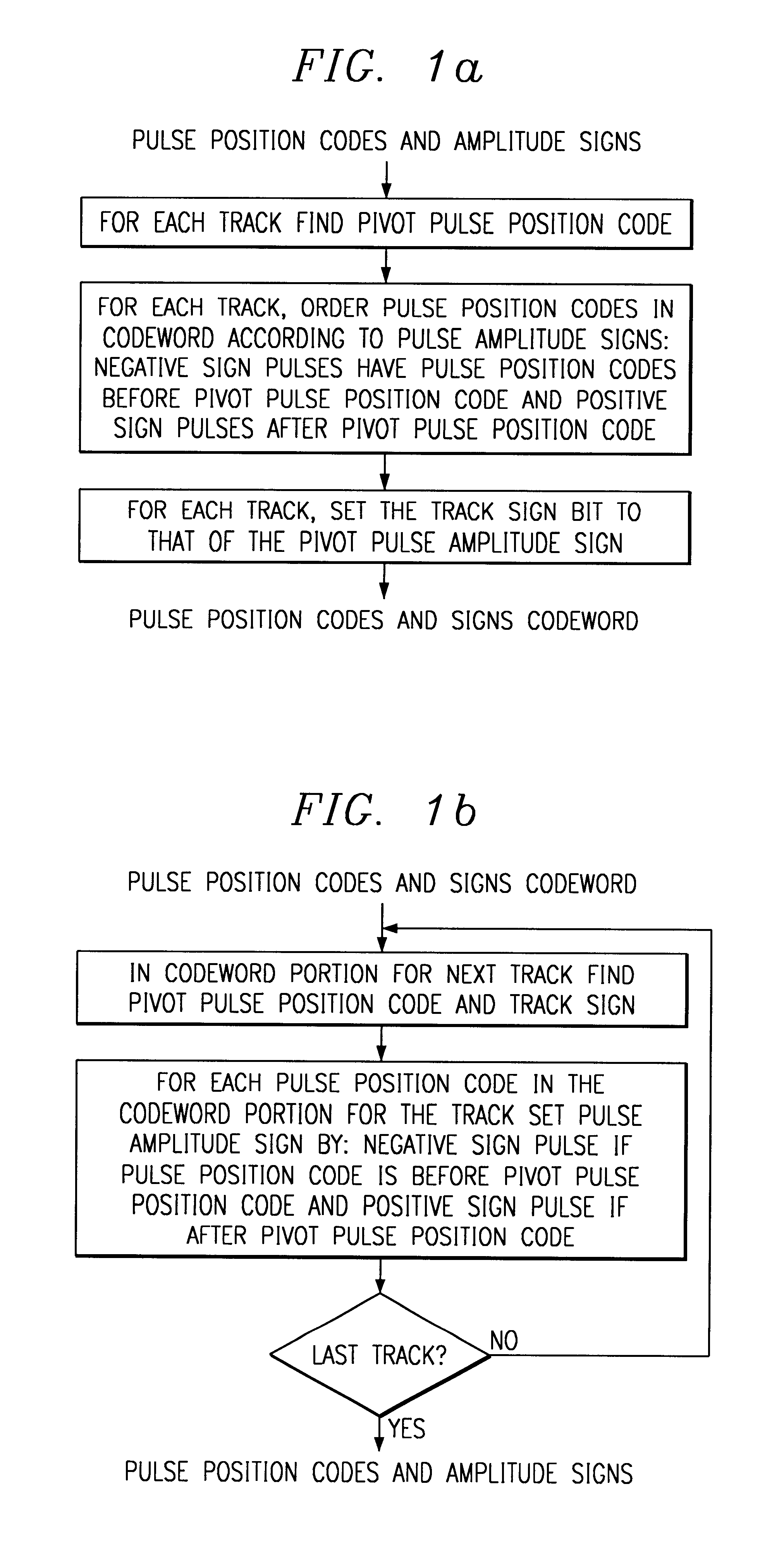
The preferred embodiment systems include preferred embodiment speech encoders and decoders which use algebraic codebooks wherein the order of the pulse position codes within a codeword encode the pulse amplitude signs. In particular, for each track of pulse positions, one of the pulses is chosen as the pivot pulse, and all other pulses in the track with position codes listed prior to the pivot pulse position code will have negative pulse amplitude signs, and all pulses with position codes listed after the pivot pulse position code will have positive pulse amplitude signs. Hence, only the sign of the pivot pulse (1 bit) need be encoded for all pulses in a track, so there will be a single track sign bit. The pivot pulse needs to be uniquely identifiable among the pulses in the track; for example, the pivot pulse could be the pulse with the smallest pulse position in the track. Decoding for a track simply finds the pivot pulse position and deduces the remaining pulse amplitu...


PUM


Abstract

Code-excited linear prediction speech encoders / decoders with excitation including an algebraic codebook contribution encoded with a single sign bit for each track of pulses by inferring pulse amplitude signs from the pulse position code ordering within a codeword.

Description

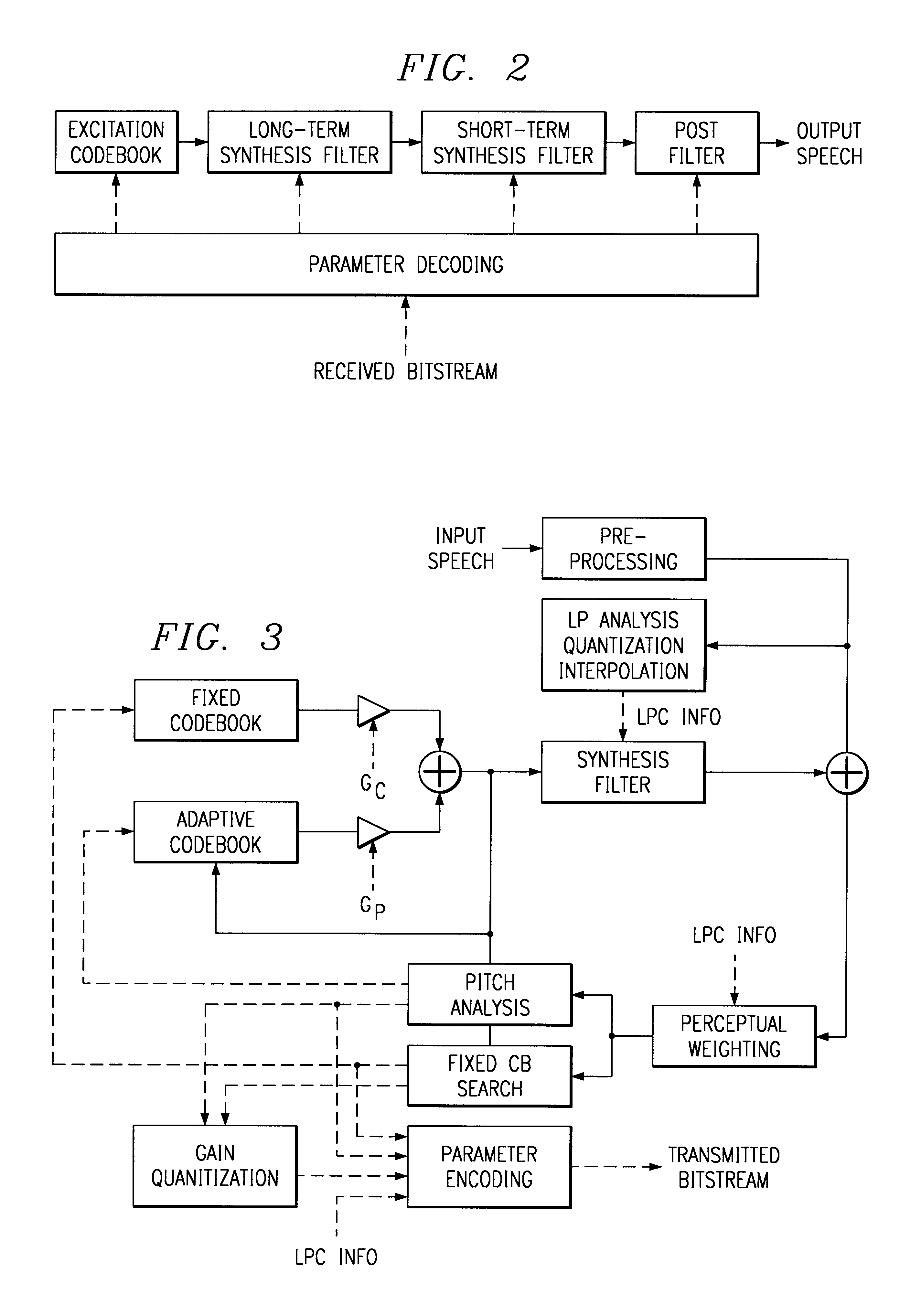
BACKGROUND OF THE INVENTIONThe invention relates to electronic devices, and, more particularly, to encoding and decoding with algebraic codebooks and systems employing such algebraic codebooks.The performance of digital speech systems using low bit rates has become increasingly important with current and foreseeable digital communications. Both dedicated channel and packetized-over-network (VolP) transmission benefit from compression of speech signals. The widely-used linear prediction (LP) digital speech coding compression method models the vocal tract as a time-varying filter and a time-varying excitation of the filter to mimic human speech. Linear prediction analysis determines LP coefficients a(j), j=1, 2, . . . , M, for an input frame of digital speech samples {s(n)} by settingr(n)=s(n)−ΣM≧j≧1a(j)s(n−j)  (1)and minimizing Σr(n)2. Typically, M, the order of the linear prediction filter, is taken to be about 10-12; the sampling rate to form the samples s(n) is typically taken to ...

Claims


Application Information

Patent Timeline
Patent Type & Authority Patents(United States)
IPC IPC(8): G10L19/00G10L19/10
CPCG10L19/10G10L2019/0008
Inventor BERNARD, ALEXIS P.
Owner TEXAS INSTR INC
Learn More