Card edge contact including compliant end

a card edge and compliant technology, applied in the direction of multi-conductor cable end pieces, fixed connections, coupling devices, etc., can solve the problems of weakening the spring force exerted at the opposite end the disadvantage of the compliant pin type, and the operator's excessive for

Inactive Publication Date: 2005-02-01
COMMSCOPE TECH LLC
View PDF50 Cites 66 Cited by
  • Summary
  • Abstract
  • Description
  • Claims
  • Application Information

AI Technical Summary

Benefits of technology

One aspect of the present disclosure relates to a mount apparatus having a separate spring contact and wire wrap pin assembly as well as h...

Problems solved by technology

During assembly, it might be possible for the operator to apply excessive force in driving the wire or cable onto a wire wrap pin/spring contact.
The excessive force tends to push the wire wrap pin/spring contact out of a re...

Method used


Image

  • Card edge contact including compliant end
  • Card edge contact including compliant end
  • Card edge contact including compliant end

Examples


Embodiment Construction

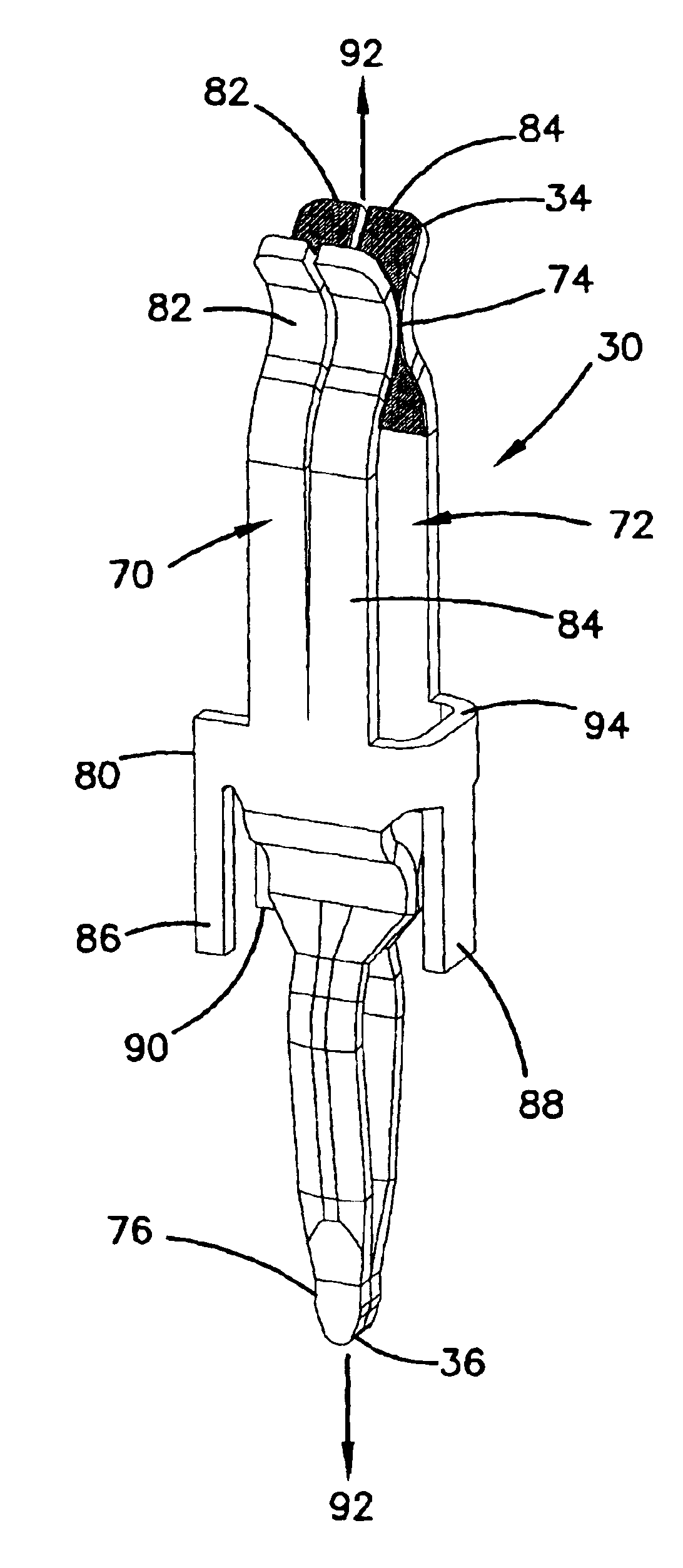
The mount apparatus of the present disclosure receives a jack assembly in a cross-connect system and retains separate spring contacts and wire wrap pins of the mount apparatus. The mount apparatus is configured and arranged in a multi-layer or sandwich construction to prevent the spring contacts and wire wrap pins from being pushed out of their retention positions.

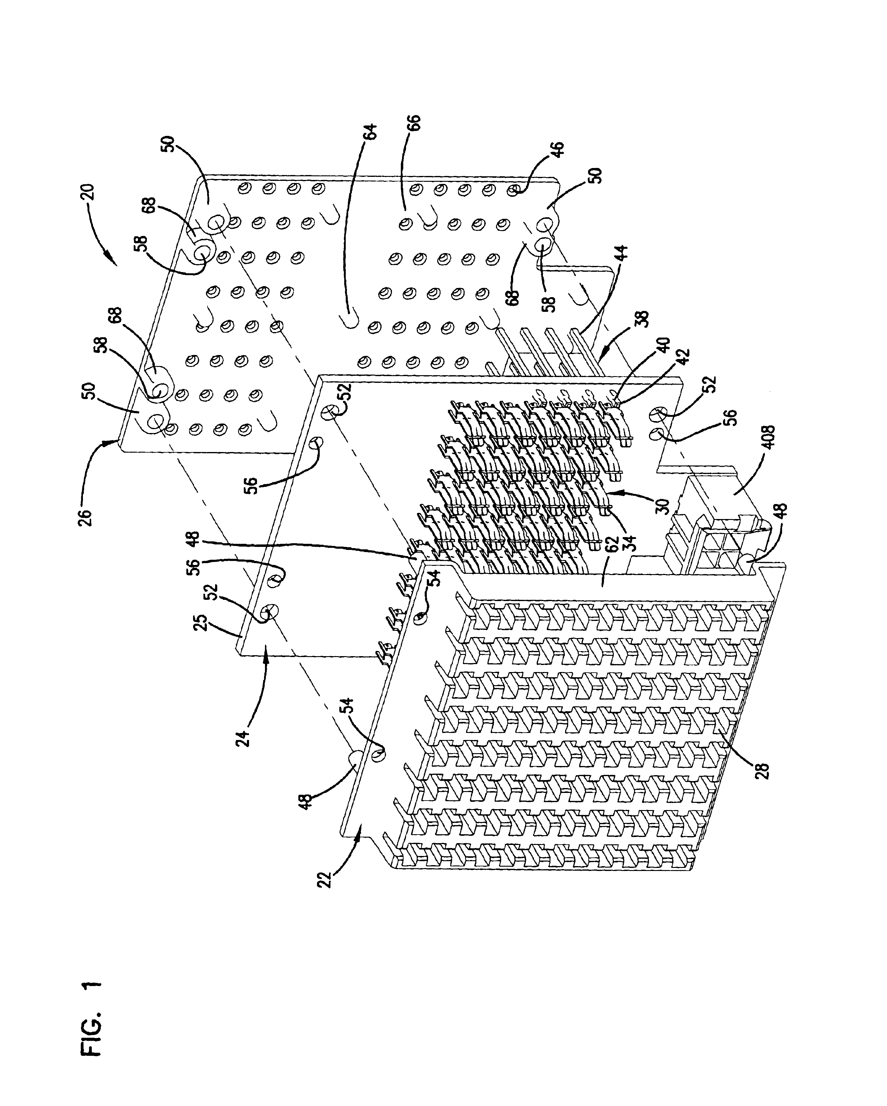
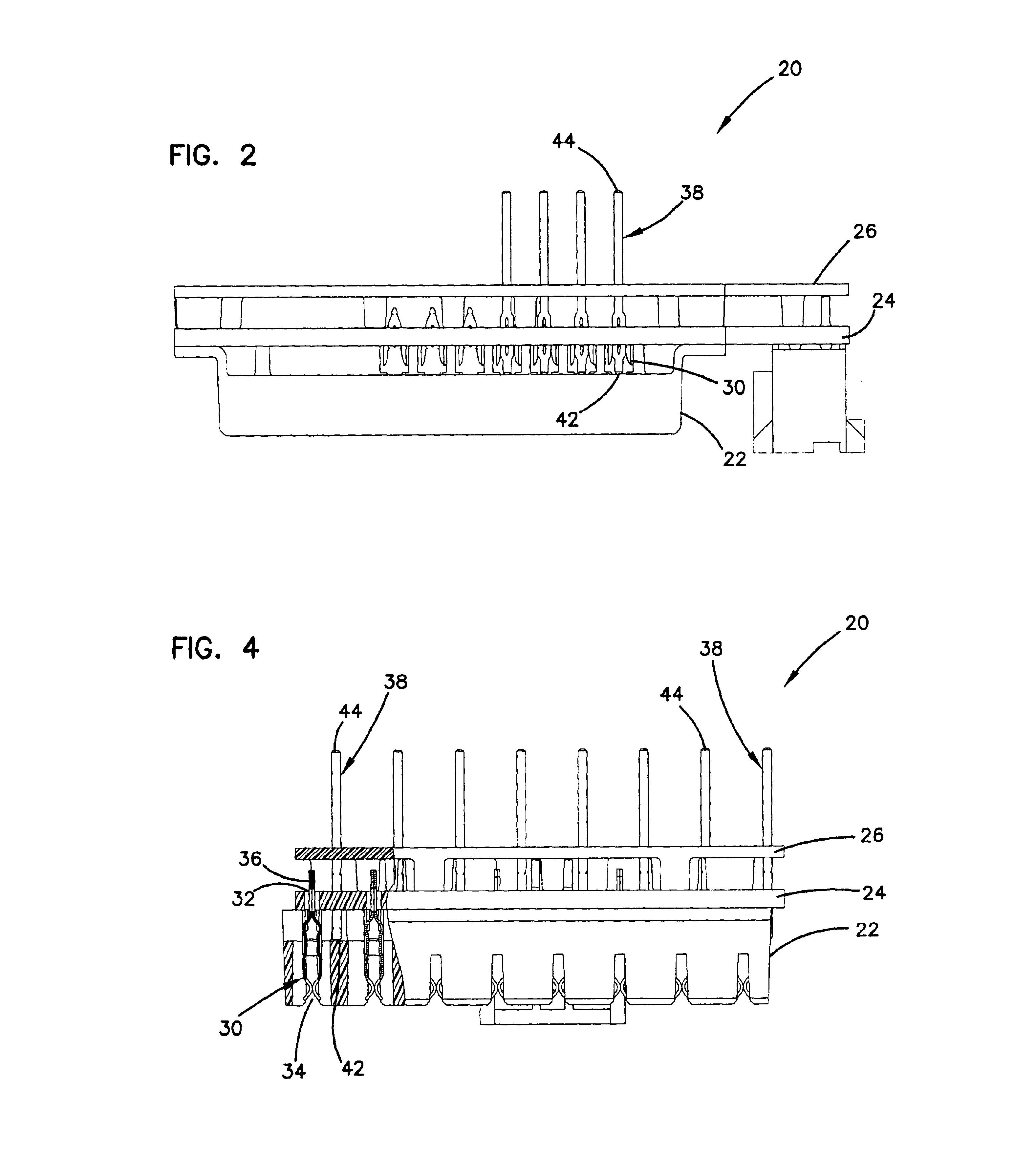
Referring now to the figures, one example embodiment of a mount apparatus 20 is shown in FIG. 1 in exploded view. The mount apparatus 20 includes a front cover 22, a circuit board assembly 24, and a back cover 26. The circuit board assembly 24 is sandwiched between the front cover 22 and the back cover 26. The front cover 22 of the mount apparatus 20 includes arrays of receptacles 28 capable of receiving a plurality of jack circuit boards as shown in the '568 patent and the '249 patent herein incorporated by reference in their entirety. As shown in these patents, a jack circuit board includes, at one end, a plurality of ja...


PUM


Abstract

An electrical terminal is adapted for insertion into a through hole of a circuit board and includes a first section that receives an electrical contact. The first section includes first and second spring arms proximate to each other at a contact point and configured to exert a first spring force to retain the electrical contact. The electrical terminal also includes a second section adapted for insertion into the through hole of the circuit board. The second section includes first and second pin members proximate to each other and defining first and second slots configured to exert a second spring force to retain the electrical terminal in the through hole of the circuit board. The second spring force is exerted in a direction perpendicular to the first spring force.

Description

FIELD OF THE INVENTIONThe present invention relates to cross-connect systems and, in particular, to a compliant pin for insertion into a circuit board assembly.BACKGROUNDA digital cross-connect system (DSX) provides a location for interconnecting two digital transmission paths. DSX is generally located in one or more frames or bays in a central office, e.g. a central telephone office. DSX also provides jack access to the transmission paths.DSX jacks are known in the art to provide spring contacts for receiving tip and ring plugs. The jacks are commonly ganged in a common housing that is mounted on a frame. The jacks are typically hard wired to wire termination pins or other connection locations that are mounted on a side of the housing opposite plug access openings.Recent DSX systems include U.S. Pat. No. 4,840,568 (the '568 patent) and U.S. Pat. No. 5,393,249 (the '249 patent), commonly assigned to ADC Telecommunications, Inc., and are incorporated herein by reference. In assemblin...

Claims


Application Information

Patent Timeline
IPC IPC(8): H01R13/11H01R12/00H01R11/22H01R12/04H01R13/42H01R11/11H01R12/58
CPCH01R12/585Y10S439/943
Inventor NORRIS, JEFFREY J.
Owner COMMSCOPE TECH LLC
Why Eureka
Try Eureka