Resilient Spinal Rod System With Controllable Angulation

Active Publication Date: 2009-02-26
LIFE SPINE INC
View PDF27 Cites 80 Cited by
  • Summary
  • Abstract
  • Description
  • Claims
  • Application Information

AI Technical Summary

Benefits of technology

[0015]The present invention provides a resilient spinal rod/rod system with controllable angulation or curvature. The present spinal rod is particularly, but not necessarily, for poster

Problems solved by technology

In the case of degenerative disc disease, spinal trauma and the like, such conditions are often painful and/or physically deforming.
A drawback of rigid fixation relates to the loading that occurs on the stabilizing assemblies and especially on the anchoring sites during n

Method used


Image

  • Resilient Spinal Rod System With Controllable Angulation
  • Resilient Spinal Rod System With Controllable Angulation
  • Resilient Spinal Rod System With Controllable Angulation

Examples


Embodiment Construction

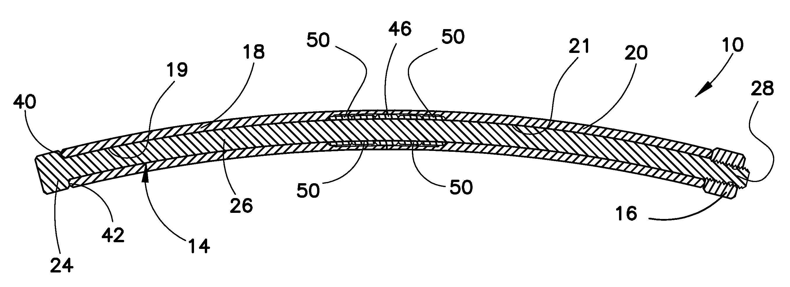
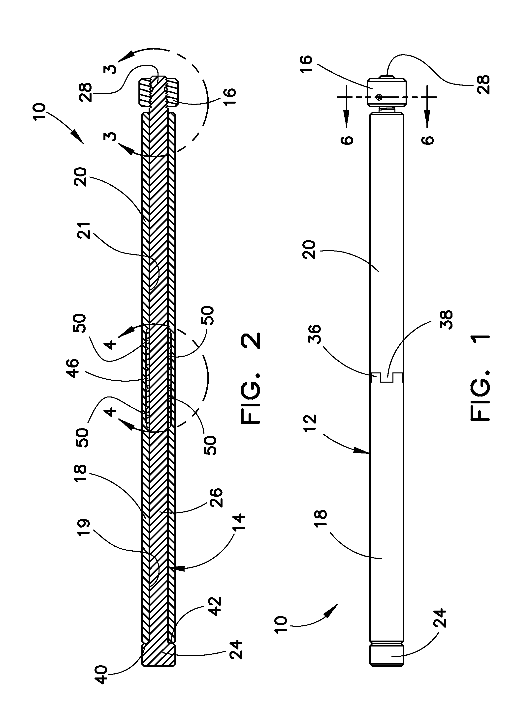
[0033]Referring to the figures, there is depicted an embodiment of a resilient spinal rod / rod system with controllable angulation (bending or curving) 10 (generally, spinal rod 10), fashioned in accordance with the present principles and especially for use in a spinal stabilization system or assembly. The spinal rod 10 is designed to be retained at both ends to respective bone anchoring elements (not shown) such as are known in the art. The spinal rod 10 is fashioned from a biocompatible material such as titanium, stainless steel or the like.

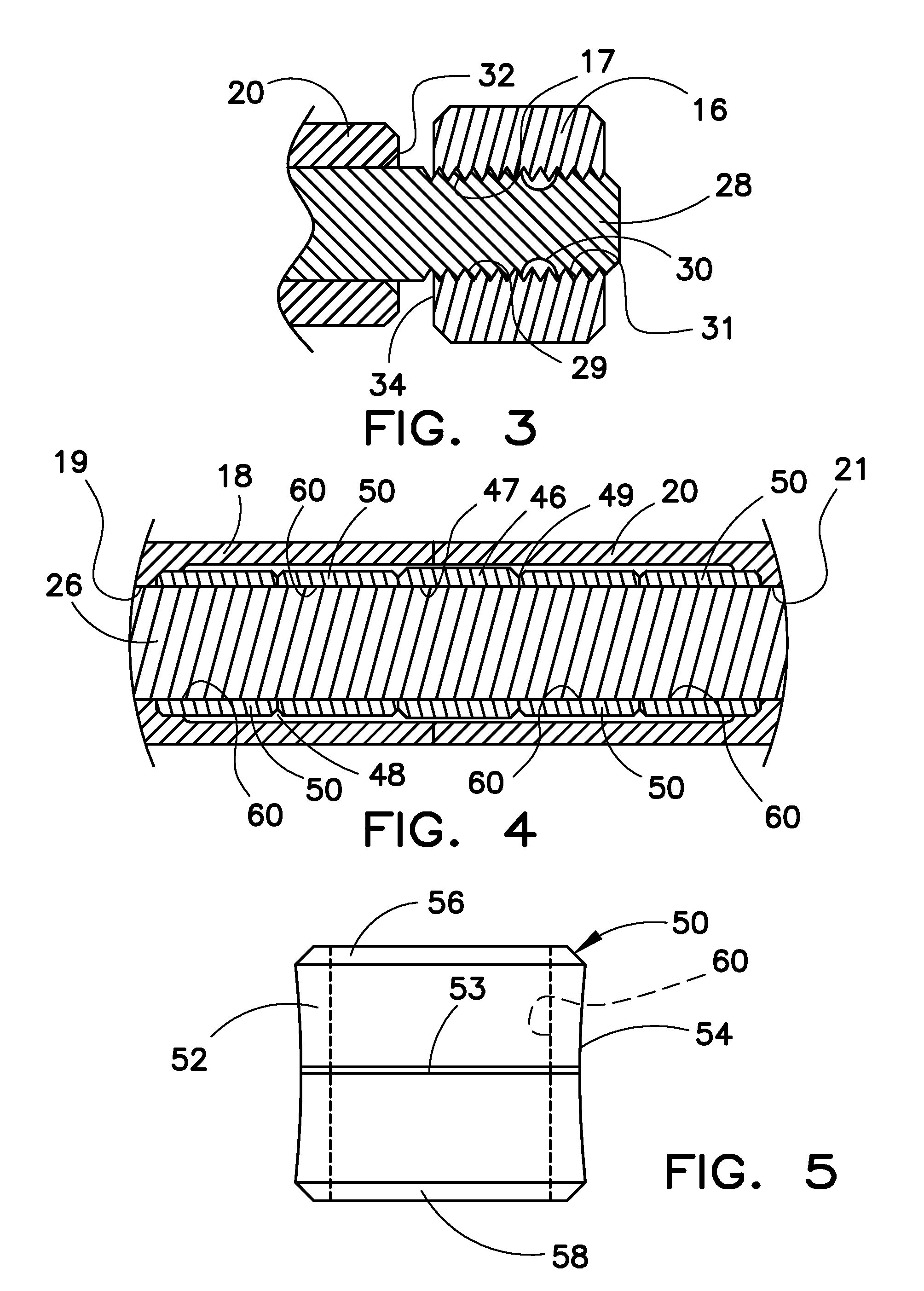
[0034]The spinal rod 10 is characterized by a rod tube or cylinder 12 that surrounds a portion of a spring rod 14. The rod tube 12 is preferably, but not necessarily, formed by first and second rod tube portions 18 and 20. The first and second rod tube portions 18 and 20 each have a first end that is stepped or castled, i.e. ends 36 and 38 of respective first and second rod tube portions 18 and 20, that are joined together at an approximate mid ...


PUM


Abstract

A spinal rod/rod system for spinal stabilization is controllably bendable or flexible along its longitudinal axis to achieve a particular radius of curvature, flex, arch or angle of the spinal rod and preserve the achieved angle through a locking mechanism. The spinal rod is controllably bendable through application of a controlled axial force. Such controllable curvature allows for limited movement of the vertebrae connected by the present resilient spinal rod system. The present spinal rod is defined by a multi-component system which includes an inner spring rod and an outer rod tube. An angulation ring is threadedly attached to an end of the spring rod and provides controlled adjustment of the angle or curvature of the spinal rod through axial compression of the spring rod relative to the outer tube. Locking prevents the increase and/or decrease of angulation of the spinal rod. A titanium spacer ring may be provided that is situated between the spring rod and the outer rod tube in order to prevent and/or hinder over angulation. One or more spacer rings may be situated between the spring rod and the outer rod tube axially adjacent each side of the titanium spacer ring that act as an additional spring force in bending, and act as a shock absorber in the axial compression of the of the spinal rod. The rings may be made of various durometers.

Description

RELATED APPLICATIONS[0001]This patent application claims the benefit of and / or priority to U.S. Provisional Patent Application Ser. No. 60 / 965,971 filed Aug. 23, 2007, entitled “Resilient Spinal Rod System With Controllable Angulation” the entire contents of which is specifically incorporated herein by this reference.BACKGROUND[0002]1. Field of the Invention[0003]The present invention relates to devices for the stabilization of the spinal column such as and particularly spinal rods for the stabilization of vertebrae of the spine and, more particularly, to a resilient spinal rod system for the stabilization of vertebrae of the spine.[0004]2. Background Information[0005]A significant portion of the population suffers from spinal problems. Such spinal problems may be attributable to disease, trauma and / or other event. In the case of degenerative disc disease, spinal trauma and the like, such conditions are often painful and / or physically deforming. Depending on the situation the pain a...

Claims


Application Information

Patent Timeline
IPC IPC(8): A61B17/70
CPCA61B17/7029A61B17/7013
Inventor BUTLER, MICHAEL S.HARTSELL, BRIAN D.
Owner LIFE SPINE INC
Why Eureka
Try Eureka