
Truncated dummy plate for process furnace

a technology of dummy plates and furnaces, applied in the field of dummy plates, can solve the problems of reducing wafer throughput and processing efficiency, consuming large quantities of process gas by apcvd systems, and often showing poor step coverage, so as to facilitate the deposition of films, promote substantially uniform flow of process gas, and uniform thickness

Inactive Publication Date: 2005-02-01
TAIWAN SEMICON MFG CO LTD
View PDF19 Cites 36 Cited by
  • Summary
  • Abstract
  • Description
  • Claims
  • Application Information

AI Technical Summary

Benefits of technology

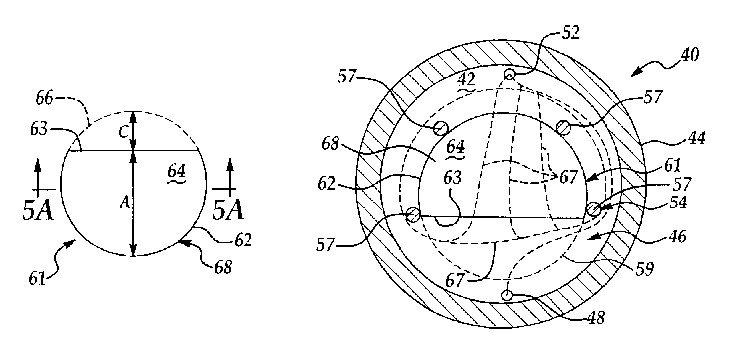
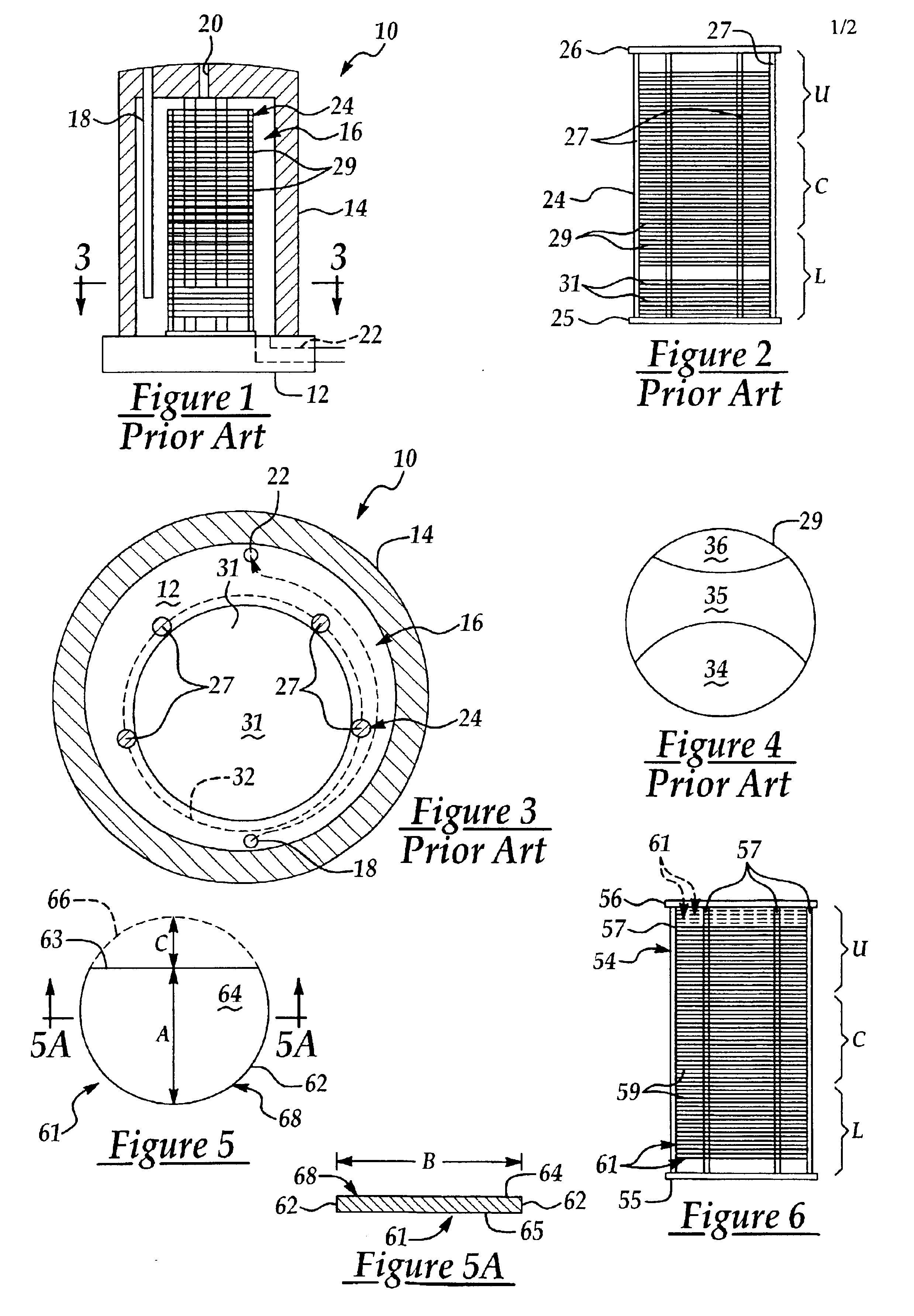
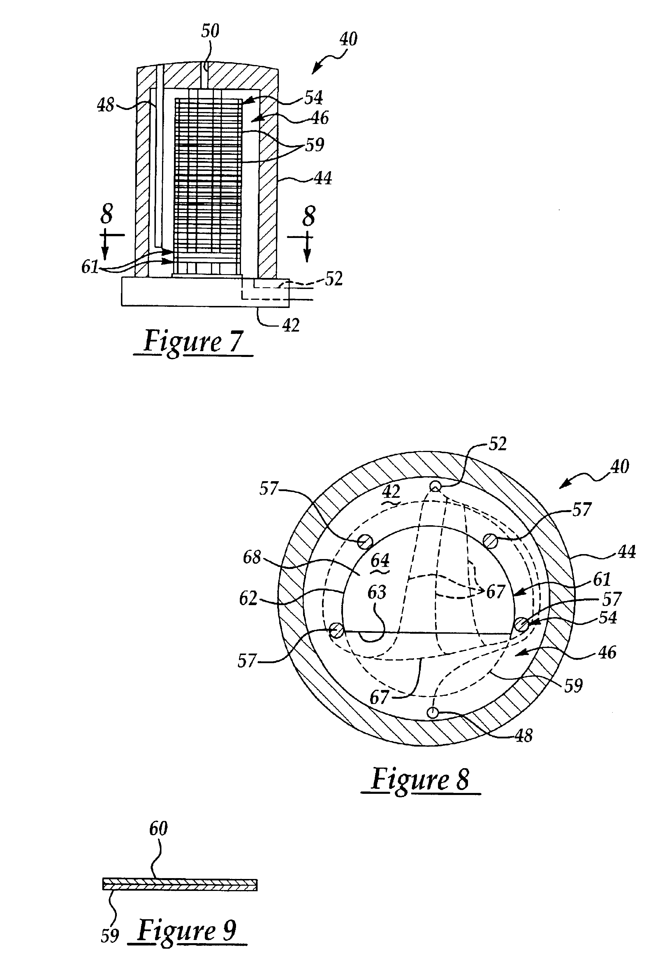
In accordance with these and other objects and advantages, the present invention is generally directed to a truncated dummy plate which is particularly suitable for promoting substantially uniform flow of process gases among all regions on the surface of a substrate to facilitate deposition of a film having uniform thickness on the substrate. The truncated dummy plate has a generally circular shape with a flat edge provided in the curved edge of the dummy plate. At least two, and preferably, about three or four of the dummy plates are positioned in the sites on a wafer boat which are in relatively close proximity to a gas outlet in a process furnace typically during a LPCVD process carried out in the furnace. The flat or truncated edges of the dummy plates are disposed on the gas inlet side of the process chamber, with the round edges of the dummy plates disposed on the gas outlet side of the process chamber. The truncated shape of the dummy plates promotes a more uniform flow of the process gases over the surfaces of substrates positioned in the wafer boat in proximity to the gas outlet, resulting in deposition of material films having a substantially uniform thickness among all regions on the surfaces of the substrates.

Problems solved by technology

While APCVD systems have high equipment throughput, good uniformity and the capability to process large-diameter wafers, APCVD systems consume large quantities of process gas and often exhibit poor step coverage.
This reduces wafer throughput and processing efficiency.

Method used


Image

  • Truncated dummy plate for process furnace
  • Truncated dummy plate for process furnace
  • Truncated dummy plate for process furnace

Examples


Embodiment Construction

The present invention includes a truncated dummy plate which promotes substantially uniform flow of process gases among all regions on the surface of a substrate to facilitate deposition of a film having uniform thickness on the substrate. At least two, and preferably, about three of the dummy plates are positioned in the sites on a wafer boat which are in relatively close proximity to a gas outlet in a process chamber, typically a LPCVD furnace, during a LPCVD process carried out in the furnace. The truncated shape of the dummy plates promotes a more uniform flow of the process gases over the surfaces of substrates positioned in the wafer boat in proximity to the gas outlet, resulting in deposition of material films having a substantially uniform thickness among all regions on the surfaces of the substrates.

Referring to FIG. 5, a truncated dummy plate 61 of the present invention includes a plate body 68 having a curved edge 62 and a flat edge 63 which interrupts the curvature of th...


PUM

PropertyMeasurementUnit
distanceaaaaaaaaaa
widthaaaaaaaaaa
diameteraaaaaaaaaa

Abstract

A truncated dummy plate which is suitable for promoting substantially uniform flow of process gases among all regions on the surface of a substrate to facilitate deposition of a film having uniform thickness on the substrate. The truncated dummy plate has a circular shape with a flat edge provided in the curved edge of the dummy plate. At least two, and preferably, about three or four of the dummy plates are positioned in the sites on a wafer boat which are in relatively close proximity to a gas outlet in a process furnace typically during a LPCVD process carried out in the furnace. The flat or truncated edges of the dummy plates are disposed on the gas inlet side of the process chamber, with the round edges of the dummy plates disposed on the gas outlet side of the process chamber.

Description

FIELD OF THE INVENTIONThe present invention relates to furnaces used in the fabrication of semiconductor integrated circuits on semiconductor wafer substrates. More particularly, the present invention relates to dummy plates having a modified shape for providing uniform gas flow and heating of wafers in a process chamber, particularly a LPCVD (low pressure chemical vapor deposition) furnace.BACKGROUND OF THE INVENTIONThe fabrication of various solid state devices requires the use of planar substrates, or semiconductor wafers, on which integrated circuits are fabricated. The final number, or yield, of functional integrated circuits on a wafer at the end of the IC fabrication process is of utmost importance to semiconductor manufacturers, and increasing the yield of circuits on the wafer is the main goal of semiconductor fabrication. After packaging, the circuits on the wafers are tested, wherein non-functional dies are marked using an inking process and the functional dies on the waf...

Claims


Application Information

Patent Timeline
Patent Type & Authority Patents(United States)
IPC IPC(8): C30B25/14C23C16/44C23C16/455H01L21/00H01L21/67H01L21/673
CPCC23C16/4412C23C16/455H01L21/67303C30B25/14H01L21/67109C23C16/45591
Inventor CHEN, YEN-HSINGLEE, HSING-JUITSENG, FU-KUOLEE, CHING-LINGLIAO, KUO-HUNG
Owner TAIWAN SEMICON MFG CO LTD
Learn More