Cavity positioning tool and method

a technology for positioning tools and cavities, applied in the direction of fluid removal, borehole/well accessories, surveys, etc., can solve the problems of increasing maintenance and operation costs of wells, inaccurate and inefficient methods of positioning pumps, and clogging or vapor lock, etc., to eliminate or reduce at least some of the disadvantages and problems

Inactive Publication Date: 2005-02-08
EFFECTIVE EXPLORATION
View PDF91 Cites 52 Cited by
  • Summary
  • Abstract
  • Description
  • Claims
  • Application Information

AI Technical Summary

Benefits of technology

The present invention provides a cavity positioning tool and method that substantially eliminates or reduces at least some of the disadvantages and problems associated with previous cavity positioning tools and methods.

Problems solved by technology

Traditional methods of positioning a pump inlet are sometimes inaccurate and inefficient, leading to clogging or vapor lock and increased maintenance and operations costs for the well.

Method used


Image

  • Cavity positioning tool and method
  • Cavity positioning tool and method
  • Cavity positioning tool and method

Examples


Embodiment Construction

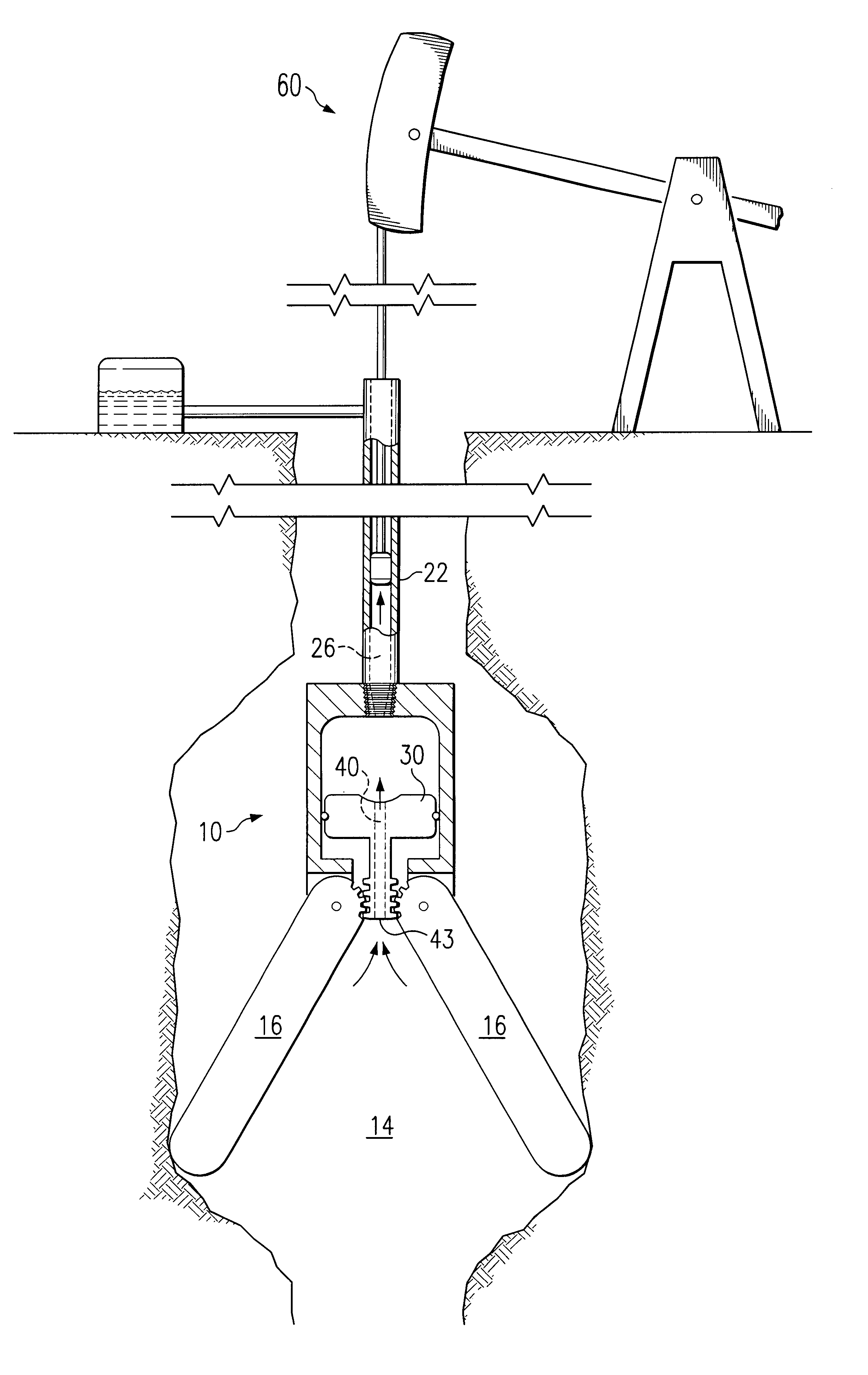
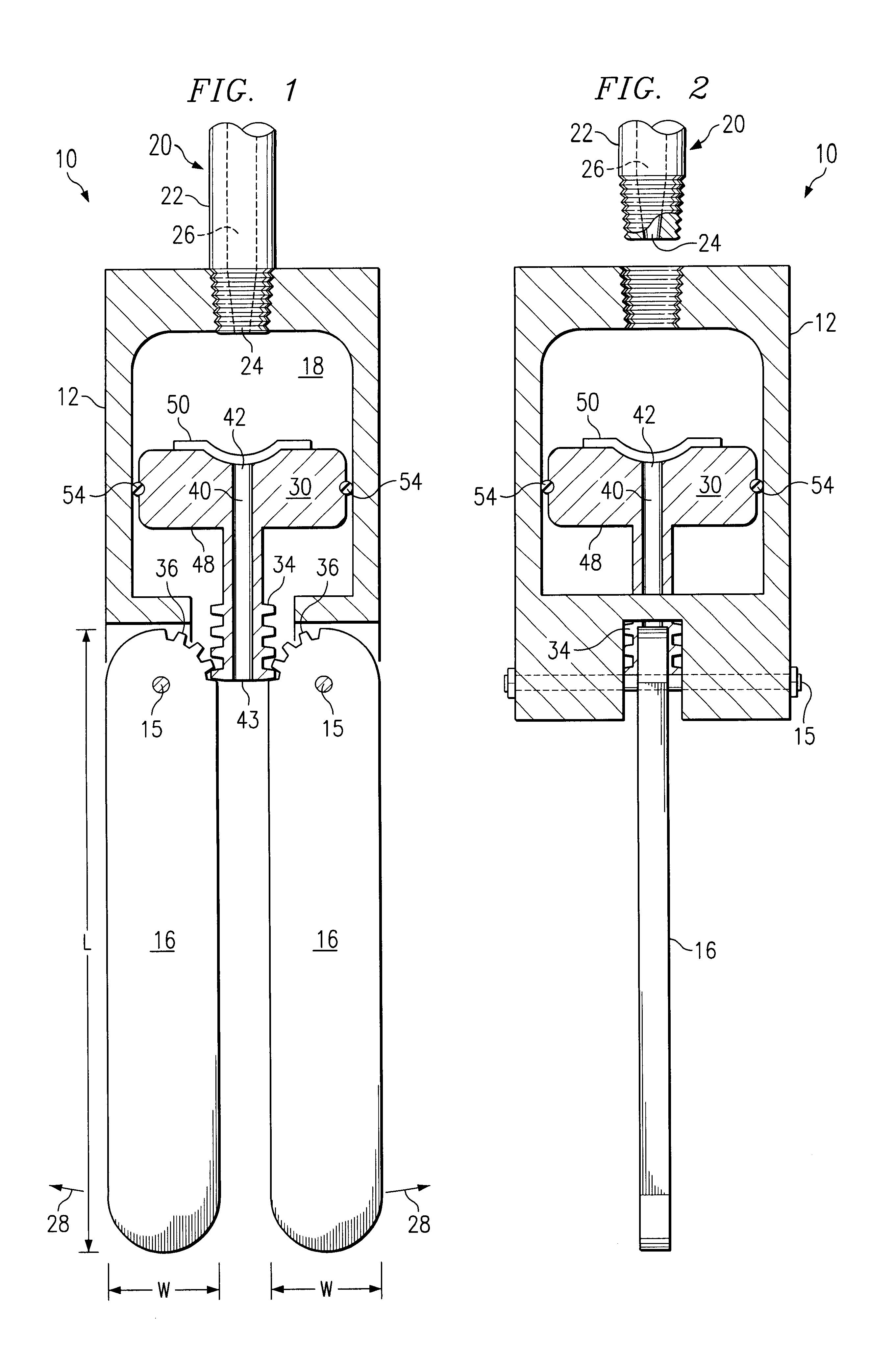
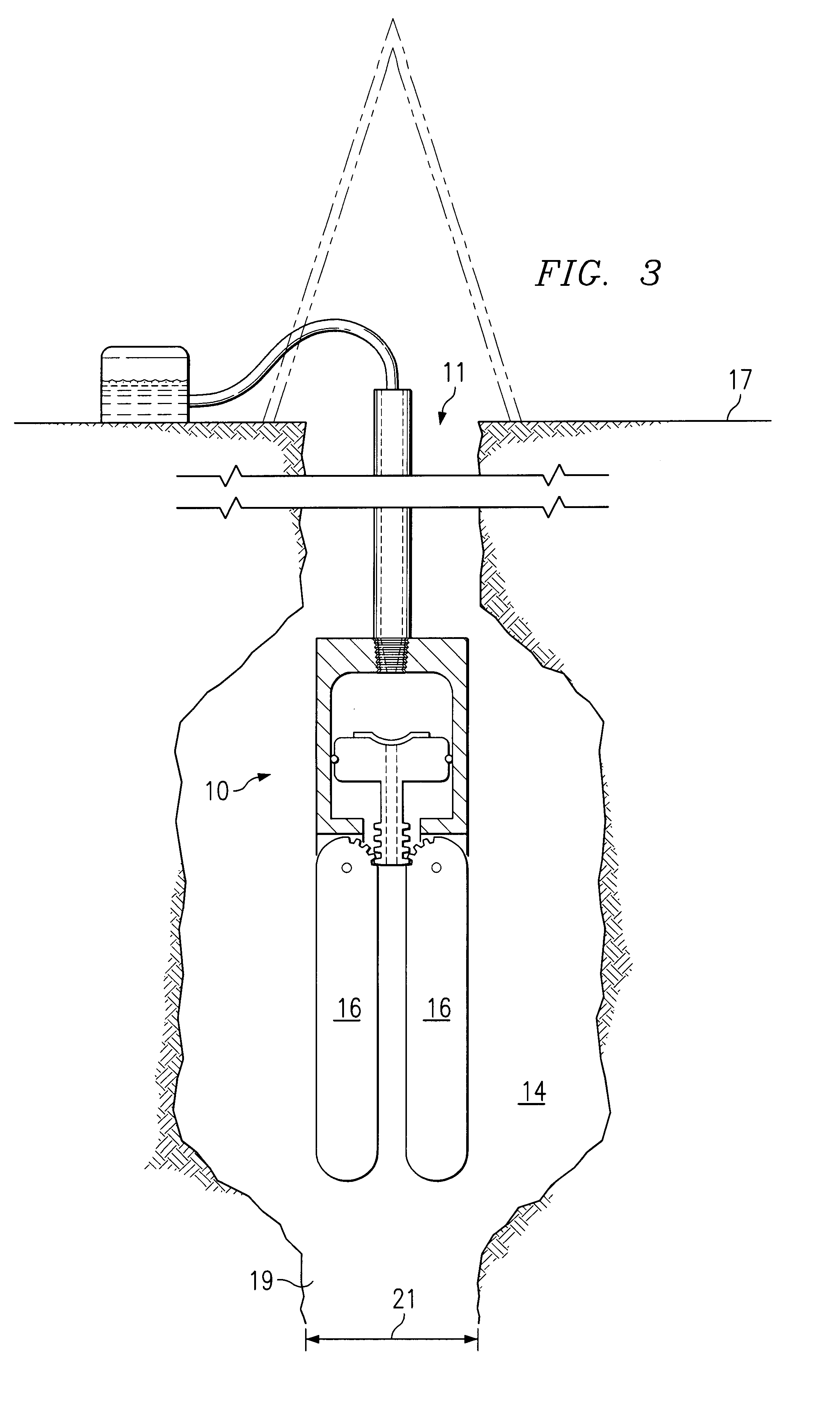
FIGS. 1 and 2 illustrate an example cavity positioning tool 10 in accordance with an embodiment of the present invention. FIG. 1 illustrates a front view, and FIG. 2 illustrates a side view, of cavity positioning tool 10. In this embodiment, cavity positioning tool 10 is adapted to position a pump inlet in a subsurface cavity. Cavity positioning tool 10 may be adapted to position other suitable devices within or in relation to a cavity. For example, motors, controllers and valves may be positioned in or relative to a cavity within cavity positioning tool 10. Cavity positioning tool 10 may be constructed of steel or other suitable materials in order to resist damage in a subsurface, downhole environment.

Cavity positioning tool 10 includes a housing 12 and blunt arms 16 pivotally coupled to housing 12. In this embodiment, cavity positioning tool 10 includes two blunt arms 16; however, cavity positioning tools in accordance with other embodiments may include either one or more than two...


PUM


Abstract

A cavity positioning tool includes a housing adapted to be coupled to a downhole string. The cavity positioning tool includes at least one blunt arm pivotally coupled to the housing. Each blunt arm is configured to contact a surface of the cavity to position the tool in the cavity. The cavity positioning tool also includes a piston slidably disposed within the housing. The piston is operable to engage each blunt arm. The piston is also operable to receive an axial force operable to slide the piston relative to the housing. The sliding of the piston extends each blunt arm radially outward relative to the housing from a retracted position.

Description

TECHNICAL FIELD OF THE INVENTIONThis invention relates generally to the field of downhole cavity tools and more particularly to a cavity positioning tool and method.BACKGROUND OF THE INVENTIONSubsurface resources such as oil, gas and water are typically recovered by drilling a well bore from the surface to a subterranean reservoir or zone that contains the resources. The well bore allows oil, gas and water to flow to the surface under its own pressure. For low pressure or depleted zones, rod pumps are often used to retrieve the fluids to the surface.To facilitate drilling and production operations, cavities are sometimes formed in the production zone. Short extensions, or “rat holes,” are often formed at the bottom of the cavity to collect cuttings and other drilling debris. As the subsurface liquids collect in the well bore, the heavier debris falls to the bottom of the rat hole and is thereby both centralized and collected out of the cavity. To avoid being clogged with debris, a p...

Claims


Application Information

Patent Timeline
Patent Type & Authority Patents(United States)
IPC IPC(8): E21B47/04
CPCE21B47/04
Inventor ZUPANICK, JOSEPH A.DIAMOND, LAWRENCE W.
Owner EFFECTIVE EXPLORATION
Why Eureka
Try Eureka