
Artificial limbs incorporating superelastic supports

a technology of artificial limbs and supports, applied in the field of artificial limbs incorporating superelastic supports, can solve the problems of limiting the normal degree of bending, shock absorption, rotation, force exerted upon the movement of the artificial appendage, and not restoring the near-normal performance of the appendage, etc., to achieve the effect of stabilizing anatomic structures, restoring motion of non-functional limbs, and reinforcing specific regions

Inactive Publication Date: 2005-02-08
CARDIOVASCULAR TECH INC
View PDF2 Cites 61 Cited by
  • Summary
  • Abstract
  • Description
  • Claims
  • Application Information

AI Technical Summary

Benefits of technology

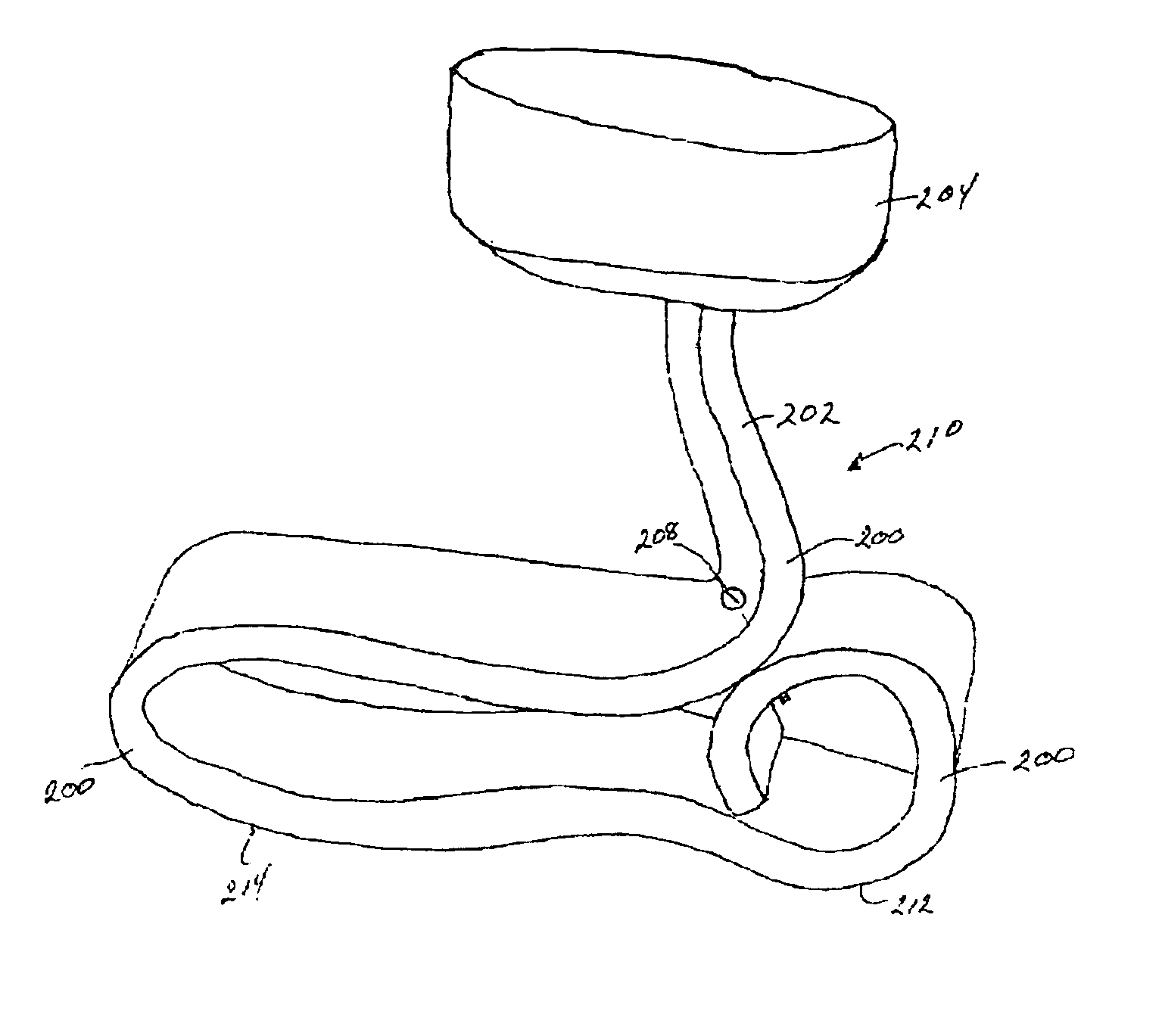
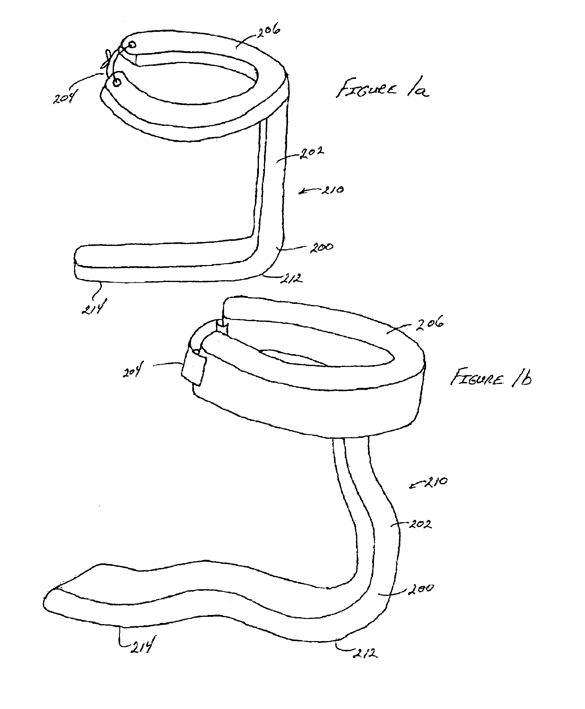
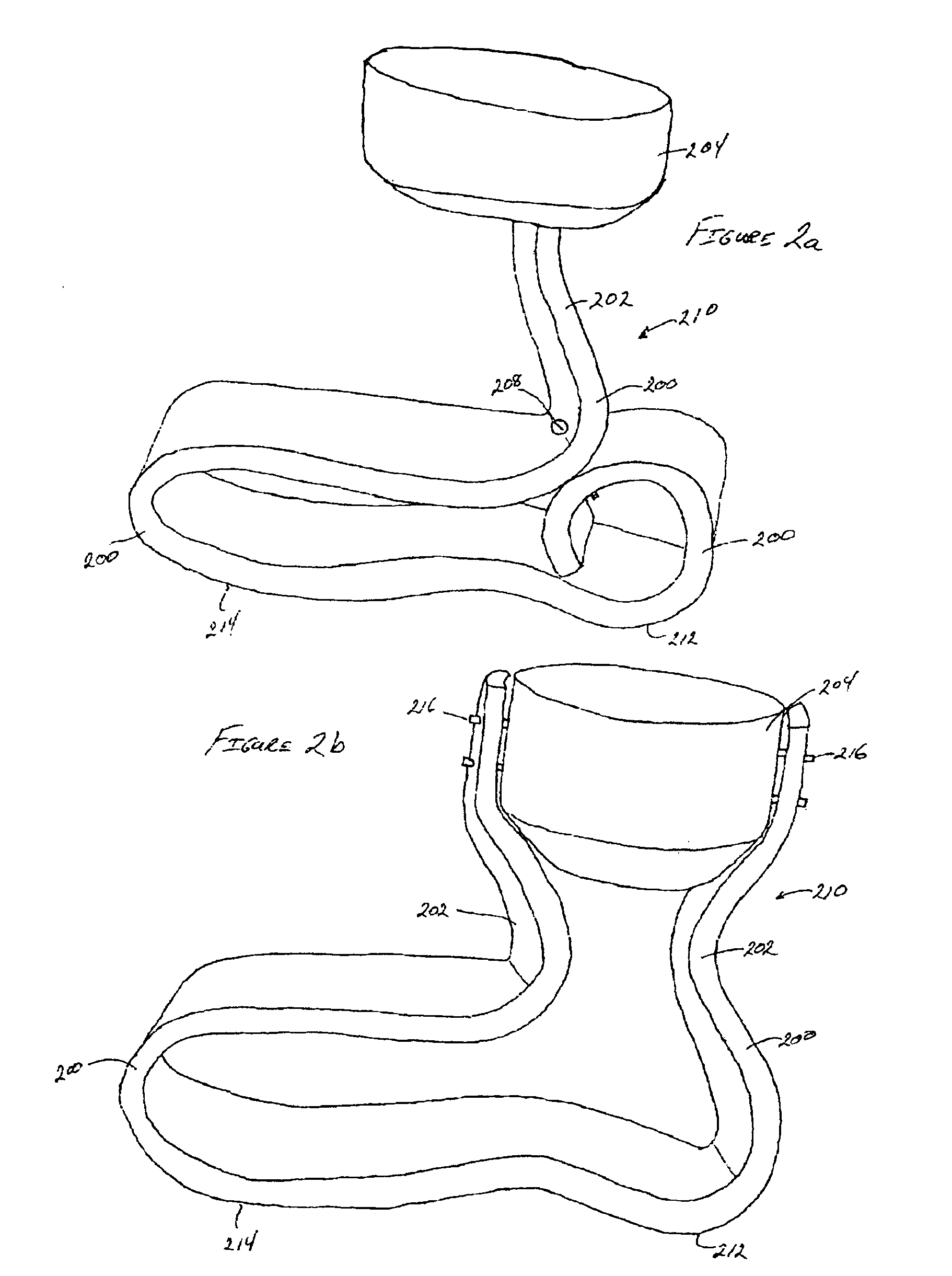
The embodiments of the present invention provide artificial limbs and braces containing superelastic supports that elastically return towards their baseline, or annealed configuration when deflected by an external force. As such these superelastic supports may be utilized in artificial limbs and braces to restore motion of the nonfunctional limb by producing an opposing force upon deflection to aid standing, walking, running, jumping, throwing, rotating, hitting, shooting, swinging, or other motion associated with physical activity.
The embodiments of the present invention also reinforce the anatomic structures, apply localized continuous compressive force against specific anatomic structures, and / or stabilize anatomic structures. As such, the artificial limbs and braces aid in healing by reinforcing specific regions and relieving stress exerted upon other regions of the body during motion of artificial limbs, or nonfunctional or less viable appendages.
The artificial limbs and braces also prevent excessive or unwanted twisting, bending, or other movement capable of causing injury or excessive stress to the anatomical joint or structures. As such, the muscles, tendons, bone interconnections, and other anatomy that enable movement at the joints are reinforced so they are less susceptible to being exposed to excess tension, stress, strain, or torque. The superelastic artificial limbs and braces of the invention also preserve the flexibility at the joint, facilitate the response to motion about the joint, and / or intensify the force exerted during movement of anatomic structures about the joint. As such, the artificial limbs and braces provide motion assistance to aid the wearer in performing an activity. In particular, the superelastic supports of the artificial limbs and braces enhance standing, bending, throwing, kicking, jumping, running, walking, hitting, shooting, or other strenuous activity by providing a directional force in response to an opposing deflection.
The artificial limbs and braces of the invention are intended to restore functionality of an amputated or nonfictional anatomic appendage. The artificial limbs and braces also reinforce the knees, ankles, elbows, wrists, shoulders (especially the rotator cuffs), neck, hips, or other anatomic joint associated with the amputated or nonfunctional anatomic appendage. The artificial limbs and braces also enable applying a specific force to tailor movement of the appendages and gradually restore operation. Artificial limbs and braces having adjustable force characteristics and / or degrees of motion may be used during the healing and training process to vary the amount of motion and strengthen tissue required to accommodate increased functionality.

Problems solved by technology

These conventional artificial limbs are extremely stiff and do not provide a broad range of dynamic response to the user during movement of the artificial limb.
As such, conventional artificial limbs limit the normal degree of bending, shock absorption, rotation, and force exerted upon movement of the artificial appendage.
These current braces are typically bulky, heavy, and severely limit any motion of the anatomy—thus they do not restore near-normal performance of the appendage.

Method used


Image

  • Artificial limbs incorporating superelastic supports
  • Artificial limbs incorporating superelastic supports
  • Artificial limbs incorporating superelastic supports

Examples


Embodiment Construction

The following is a detailed description of the presently best-known modes of carrying out the inventions. This detailed description is not to be taken in a limiting sense, but is made merely for the purpose of illustrating the general principles of the inventions.

This specification discloses a number of embodiments, mainly in the context of appendage replacement, reinforcement, and performance enhancement for artificial limbs, and braces. The appendages that the embodiments may be modified to address include the foot, the leg below the knee, the leg extending above the knee, the hand, the arm below the elbow, the arm extending above the elbow, and the arm including the shoulder. Two or more artificial limbs and braces of the invention may be combined with a variety of mechanisms that are able to coordinate the operation of the artificial limbs and braces to satisfy the performance requirements for multiple replaced appendages or nonfunctional limbs.

Nevertheless, it should be appreci...


PUM


Abstract

A method of using an artificial limb includes mounting an artificial limb to a body part, applying a force to the artificial limb to deflect the artificial limb from a first position in a first direction, and removing the force, whereby the artificial limb moves to the first position. The artificial limb includes a mounting end configured to be mounted to a body part and one or more superelastic members. The superelastic members may be made of Nitinol.

Description

TECHNICAL FIELDThis invention relates to devices for replacing specific anatomic limb regions of amputees, and restoring the performance of nonfunctional or less viable anatomic appendages. More particularly, the invention relates to supports that are incorporated in artificial limbs and braces to restore functionality of the appendages.BACKGROUNDCurrent techniques for providing artificial limbs or braces involve using stainless steel, carbon fiber laminate and composites, or semi-rigid polymers to replace the anatomic appendage. These conventional artificial limbs are extremely stiff and do not provide a broad range of dynamic response to the user during movement of the artificial limb. As such, conventional artificial limbs limit the normal degree of bending, shock absorption, rotation, and force exerted upon movement of the artificial appendage.Conventional brace configurations incorporate stainless steel, or other solid metal or alloy bar attached to the brace and incorporating ...

Claims


Application Information

Patent Timeline
IPC IPC(8): A42B3/00A42B3/04A43B13/18A61B17/80A61B17/68A61H1/02A61F2/66A61F5/01A61F2/50A61F2/60A61F2/78A61F5/02A61F5/14A63B21/02B60R22/00A61F2/00A61F2/64A61B17/00B60R21/00B60R21/02
CPCA61H1/0218A63B21/02A63B21/1449B60R22/001A43B7/1415A43B13/187A61F2/60A61F2/66A61F2/78A61F2002/608A61F2002/607A61F2002/665A61F2002/6657A61F2002/6664A61F2002/6678A61F2002/705A61F2002/7862A61F2002/7881A61F2220/0025A61F2220/0075B60R2021/0048B60R2021/022A61F2/64A61F2/6607A61F2002/30329A61F2002/30464A61F2002/5079A61F2002/6614A61F2002/30462A63B21/4025
Inventor HOUSER, RUSSELL A.HARE, WILLIAM D.
Owner CARDIOVASCULAR TECH INC
Learn More