Filter element having center piece and methods

a filter element and center piece technology, applied in the field of filter element center pieces, can solve problems such as damage to whatever system

Inactive Publication Date: 2005-02-08
DONALDSON CO INC
View PDF55 Cites 132 Cited by
  • Summary
  • Abstract
  • Description
  • Claims
  • Application Information

AI Technical Summary

Benefits of technology

A core construction for use in a filter element includes a tubular member having a wall with opposite first and second ends. The first end is adaptable for engagement with structure, such as a frame utilized with a filter element. The second end is also engageable with external structure, such as a handle. Preferably, a filter element is constructed by rolling a media construction around the core construction. The media construction includes a corrugated sheet secured to a flat sheet rolled around the core construction into a coiled construction. The coiled construction has inlet flutes and outlet flutes.

Problems solved by technology

If it is difficult or inconvenient to service the filter element, the user may delay the proper servicing, which can cause damage to whatever system is being filtered.

Method used


Image

  • Filter element having center piece and methods
  • Filter element having center piece and methods
  • Filter element having center piece and methods

Examples


Embodiment Construction

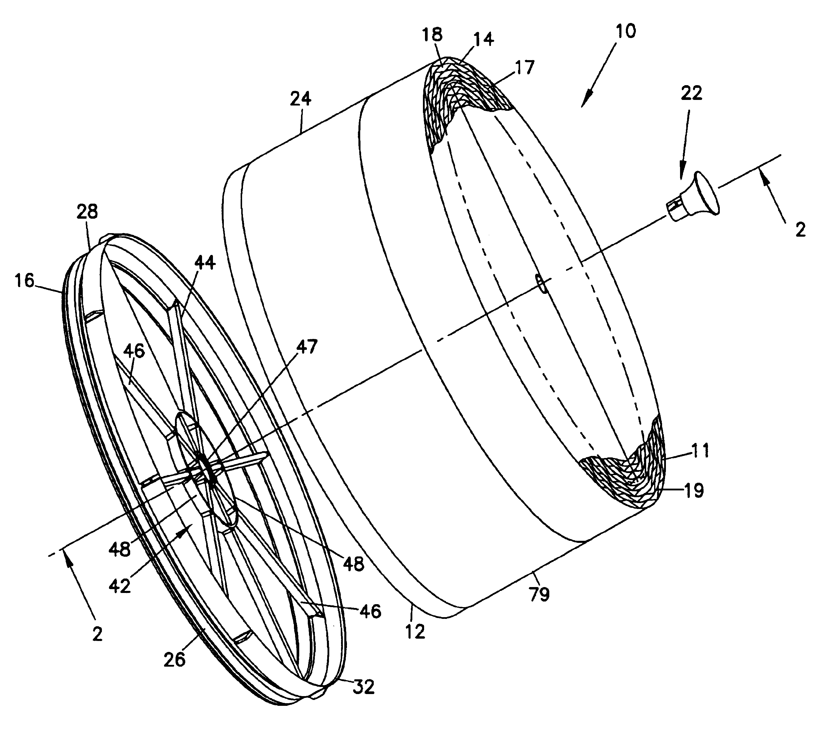
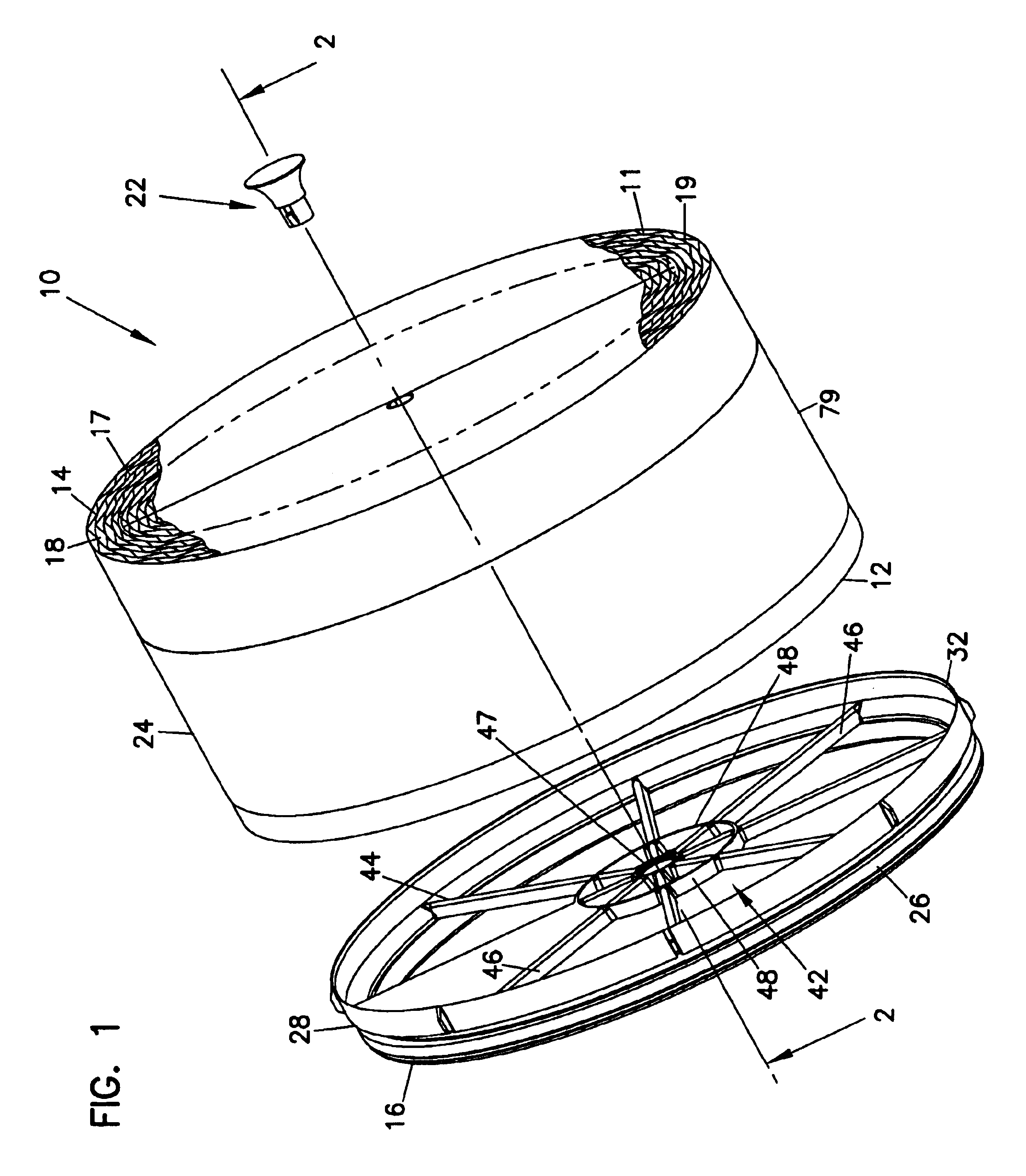
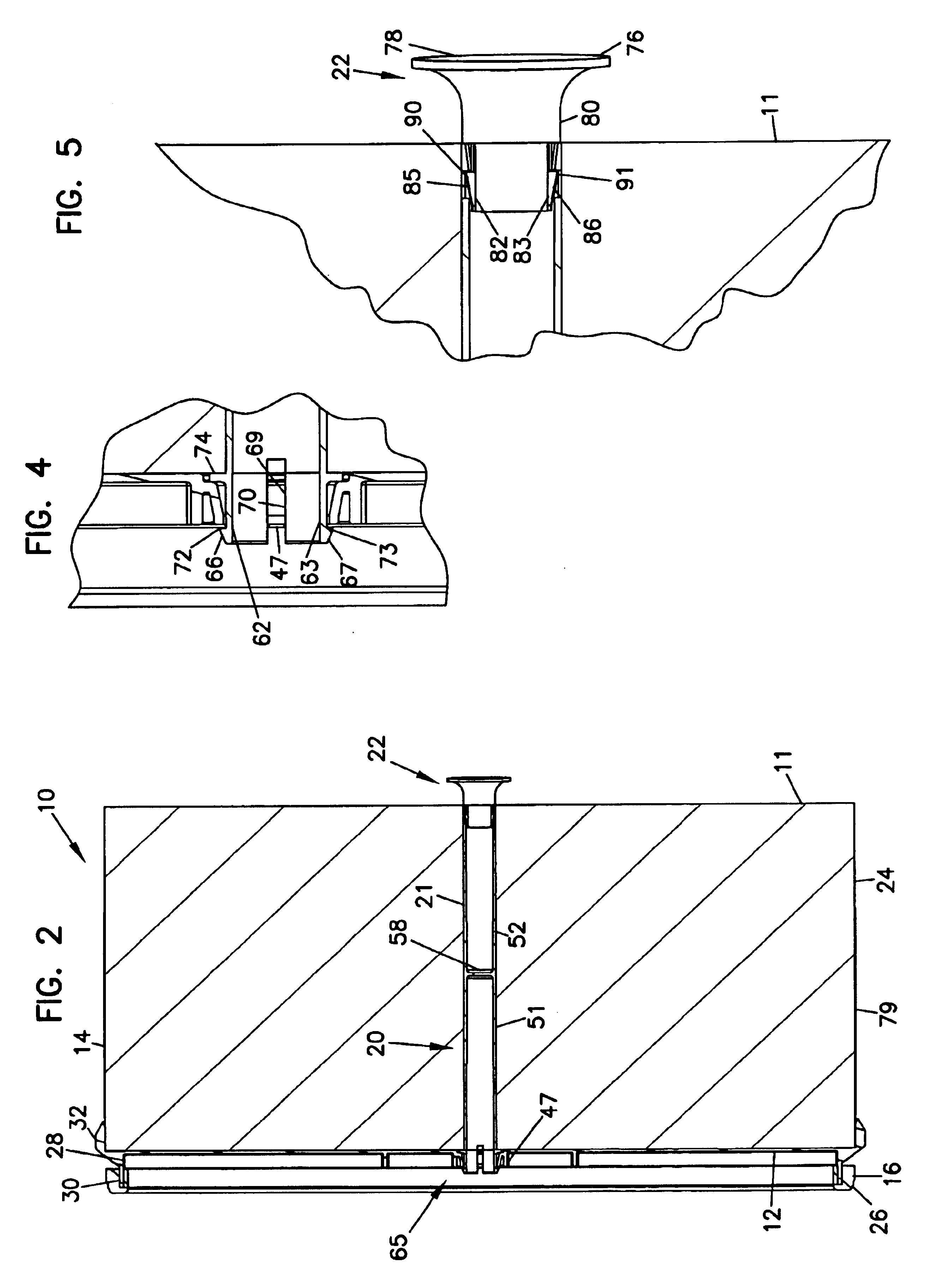
FIG. 1 depicts a filter element 10 that is usable for cleaning fluid, such as gas, in particular air. The filter element 10 is configured to permit straight through flow. By the term “straight through flow,” it is meant that the fluid flows directly through the filter element 10, entering at an inlet face 11 and exiting in a same direction at an opposite, outlet face 12 without turning a corner. The filter element 10 includes filter media 14 that is configured to filter particulates from the gas stream entering at the inlet face 11, such that the gas stream exiting the outlet face 12 is at least partially clean (i.e., free of particulates). As can also be seen in FIG. 1, the filter element 10 includes a seal member 16, which aids in inhibiting leakage between the filter element 10 and a housing or duct in which the filter element 10 is installed. The filter element 10 also includes a center piece construction 20 (FIGS. 2 and 3) of which an optional handle 22 attached thereto is visi...


PUM

PropertyMeasurementUnit
densityaaaaaaaaaa
external structureaaaaaaaaaa
dimensionsaaaaaaaaaa

Abstract

A core construction for use in a filter element includes a tubular member having a wall with opposite first and second ends. The first end is adaptable for engagement with structure, such as a frame utilized with a filter element. The second end is also engageable with external structure, such as a handle. Preferably, a filter element is constructed by rolling a media construction around the core construction. The media construction includes a corrugated sheet secured to a flat sheet rolled around the core construction into a coiled construction. The coiled construction has inlet flutes and outlet flutes. Methods for using and assembling filter elements preferably use core constructions as described herein.

Description

TECHNICAL FIELDThis disclosure describes filter constructions for filtering fluids, such as gas or liquid. In particular, this disclosure describes a filter element having a center piece and methods for using and assembling a filter element having a center piece.BACKGROUNDStraight through flow filter elements have been used in systems for cleaning fluid passing therethrough. Straight through flow filter elements typically have an inlet face and an oppositely disposed outlet face. In this manner, fluid flows in one direction upon entering the filter element at the inlet face and will have the same direction of flow as it exits the outlet face. Typically, straight through flow filter elements will be installed in a duct or housing of some type. After a period of use, the filter element will require servicing, either cleaning or a complete replacement of the filter element. If it is difficult or inconvenient to service the filter element, the user may delay the proper servicing, which ...

Claims


Application Information

Patent Timeline
Patent Type & Authority Patents(United States)
IPC IPC(8): B01D46/42B01D46/52B01D25/00B01D46/00B01D46/10
CPCB01D25/001B01D46/0004B01D46/10B01D46/4227B01D46/527B01D25/24Y10S55/05B01D2201/4084B01D2265/028B01D2271/027B01D2201/0415B01D46/00
Inventor BISHOP, WAYNE R WJULIAR, WILLIAM MICHAELXU, JIANGIESEKE, STEVEN SCOTT
Owner DONALDSON CO INC
Why Eureka
Try Eureka