Supercharge Your Innovation With Domain-Expert AI Agents!

Piping joint structure

a technology of piping joints and joints, applied in the direction of marine propulsion, vessel construction, special-purpose vessels, etc., can solve the problem of reducing the ease of workability when connecting or detaching the piping joints, and achieve the effect of preventing the diameter of the retainer sleeves

Inactive Publication Date: 2005-02-22
HONDA MOTOR CO LTD
View PDF9 Cites 19 Cited by
  • Summary
  • Abstract
  • Description
  • Claims
  • Application Information

AI Technical Summary

Benefits of technology

The present invention provides a piping joint structure with protective measures that do not impair the ease of workability of the piping joint. The structure includes a female member with a fitting hole, a male member with a cylinder portion, a flange, a retainer sleeve, a pawl, a pawl engaging portion, and a ring member. The retainer sleeve can be enlarged and reduced between a large diameter and a smaller diameter. The pawl engages the retainer sleeve and the female or male member for locking it. The ring member prevents the reduction of the diameter of the retainer sleeve. The invention also provides a fuel tank structure with a piping joint and a ring member for maintaining the holding force of the piping joint.

Problems solved by technology

However, when the piping joint is covered with a cover, the cover must be removed at the time of disengaging the piping joint, so that ease of workability when connecting or detaching the piping joint is decreased with the aforementioned arrangements of the background art.

Method used


Image

  • Piping joint structure
  • Piping joint structure
  • Piping joint structure

Examples


Embodiment Construction

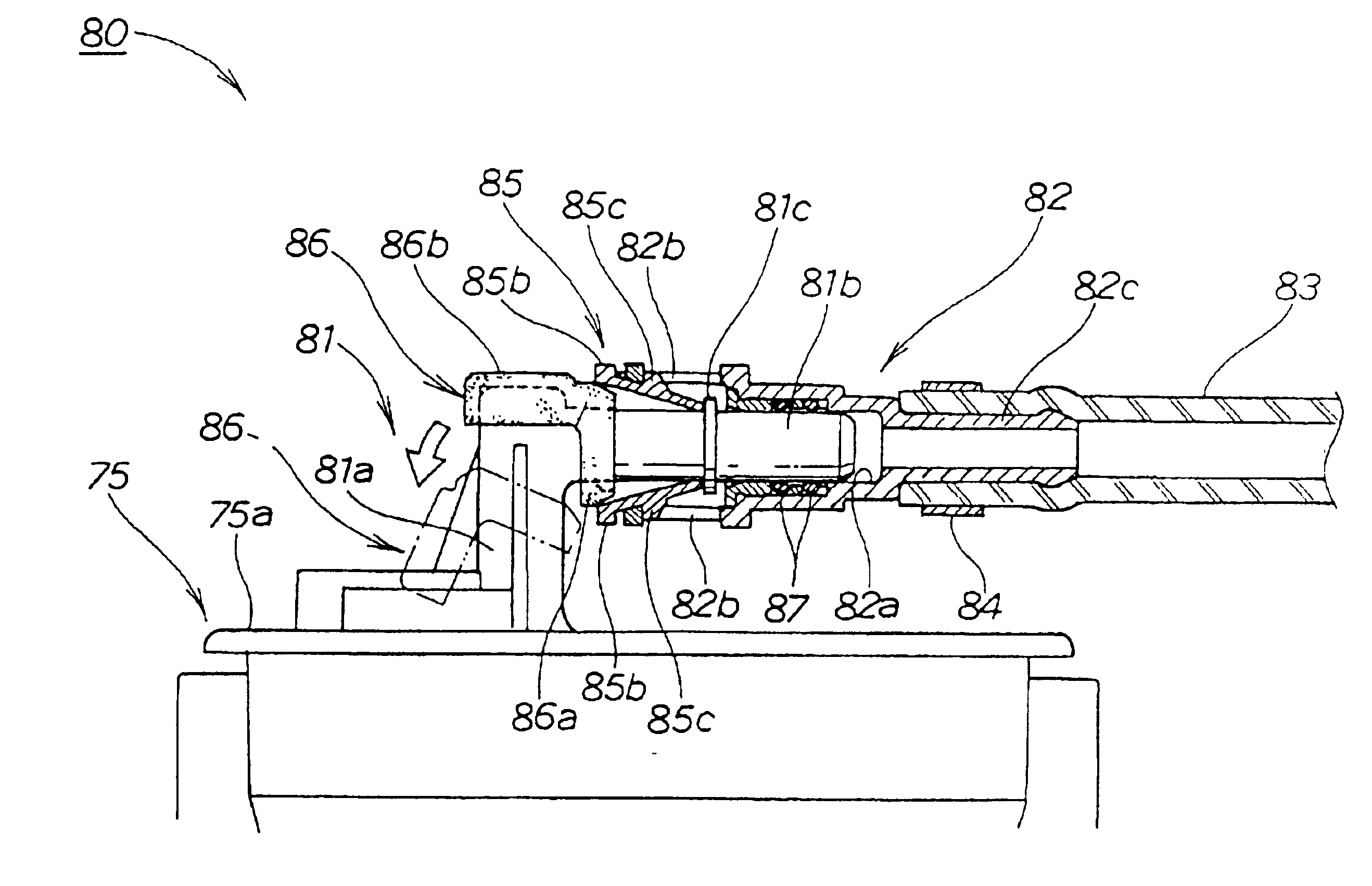
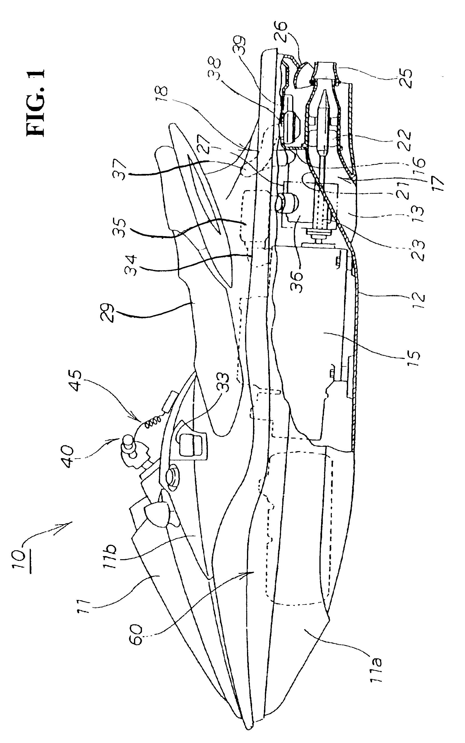
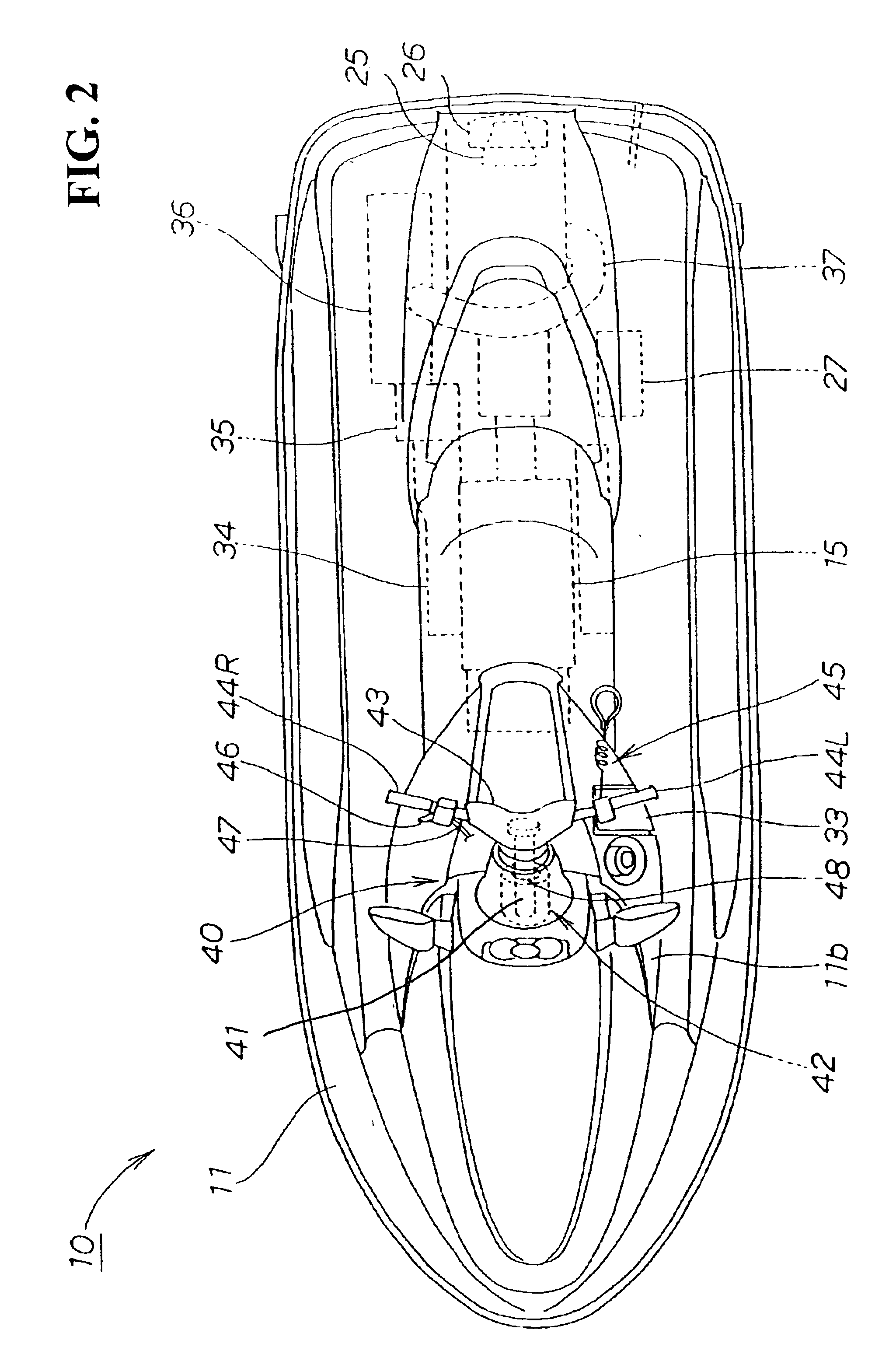
An embodiment of the present invention will hereinafter be described with reference to the accompanying drawings. FIG. 1 is a side view of a personal watercraft having a piping joint structure according to the present invention. FIG. 2 is a plan view of the personal watercraft having the piping joint structure according to the present invention. FIG. 3 is a side view of a fuel tank having the piping joint structure according to the present invention. FIG. 4 is an exploded, perspective view of the fuel tank having the piping joint structure according to the present invention. FIG. 5 is a frontal, sectional view of the piping joint structure according to the present invention in a disengaged condition. FIG. 6 is an exploded, perspective view of portions of the piping joint structure according to the present invention. FIG. 7 is a frontal, sectional view of the piping joint structure according to the present invention in a connected condition. FIGS. 8(a) and 8(b) are views of the pipin...


PUM


Abstract

A piping joint includes a male member or joint fastened to a female member or socket by locking pawls of a retainer sleeve onto pawl engaging portions. By pressing a flange by the tip ends of the pawls, the male member (joint) can be disengaged from the female member (socket) by reducing the diameter of the retainer sleeve and disengaging the pawls from the pawl engaging portions. A ring member is formed of an elastic material and is inserted between the retainer sleeve and a cylinder portion in a locked condition. A reduction of the diameter of the retainer sleeve is prevented by the presence of the ring member. Therefore, the connecting or detaching of the piping joint can be carried out in a condition where a holding force of the piping joint is maintained.

Description

BACKGROUND OF THE INVENTION1. Field of the InventionThe present invention relates to a piping joint structure, and more particularly to a piping joint structure in which a male member can be detachably connected to a female member.2. Description of the Background ArtPiping joint structures have been available in the background art. For example, (1) “Water Jet Propulsion Watercraft” described in Japanese Patent Laid-open No. Hei 7-267184, and (2) “Quick Connector and Holding Member Thereof” described in Japanese Patent Laid-open No. Hei 11-201355, the entirety of each of which is hereby incorporated by reference, are representative of joint structures of the background art.According to FIG. 6 of the 7-267184 publication, an oil supply pipe 79 is inserted into an auxiliary fuel tank 71, a transfer pipe 74 is connected to the oil supply pipe 79 through a joint 78, the transfer pipe 74 is connected to a main fuel tank 76, and oil in the auxiliary fuel tank 71 is transferred into the mai...

Claims


Application Information

Patent Timeline
Patent Type & Authority Patents(United States)
IPC IPC(8): F16L37/00F16L37/084B63B35/73B63H21/38B63H11/08F16L37/12
CPCF16L37/0987B63B2770/00Y10S285/921B60K2015/03528
Inventor NAGATA, TADAAKISHOGASE, HAJIME
Owner HONDA MOTOR CO LTD
Features
  • R&D
  • Intellectual Property
  • Life Sciences
  • Materials
  • Tech Scout
  • Unparalleled Data Quality
  • Higher Quality Content
  • 60% Fewer Hallucinations
Learn More