Automatic charging system and method of robot cleaner

a robot cleaner and charging system technology, applied in the field of robot cleaners, can solve the problems of increasing the cost of implementing the charging system of the robot cleaner, not quickly detecting the infrared signal, etc., and achieve the effect of accurately and quickly moving the robot cleaner

Active Publication Date: 2005-02-22
LG ELECTRONICS INC
View PDF4 Cites 164 Cited by
  • Summary
  • Abstract
  • Description
  • Claims
  • Application Information

AI Technical Summary

Benefits of technology

Therefore, an object of the present invention is to provide an automatic charging system and method of a robot cleaner in which a few infrared ray senso

Problems solved by technology

However, the charging system of the robot cleaner in accordance with the conventional art has the following problems.
In other words, because the robot cleaner is moved along the pre-set path to detect the infrared signal, it can not detect the infrared signal q

Method used


Image

  • Automatic charging system and method of robot cleaner
  • Automatic charging system and method of robot cleaner
  • Automatic charging system and method of robot cleaner

Examples


Embodiment Construction

Reference will now be made in detail to the preferred embodiments of the present invention, examples of which are illustrated in the accompanying drawings.

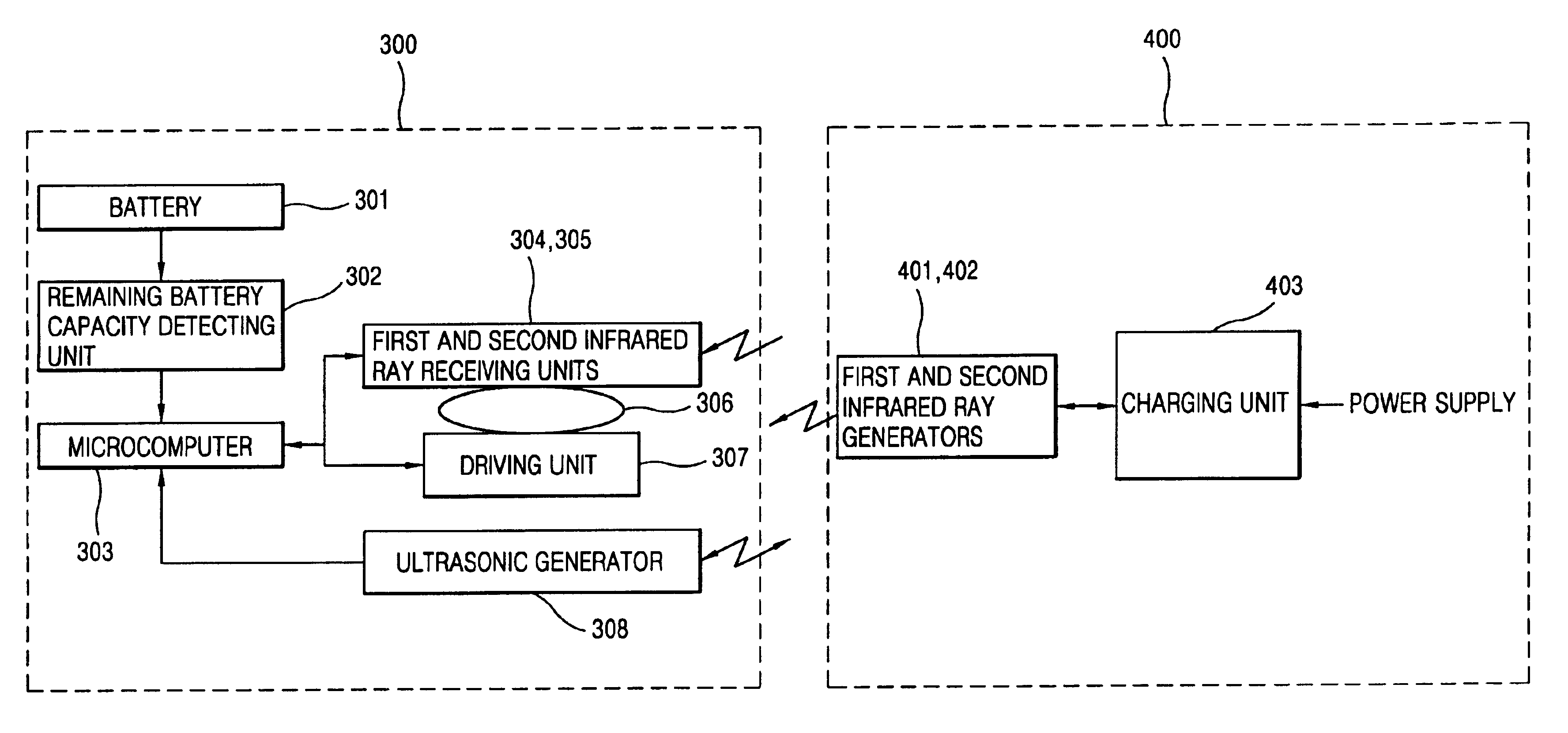
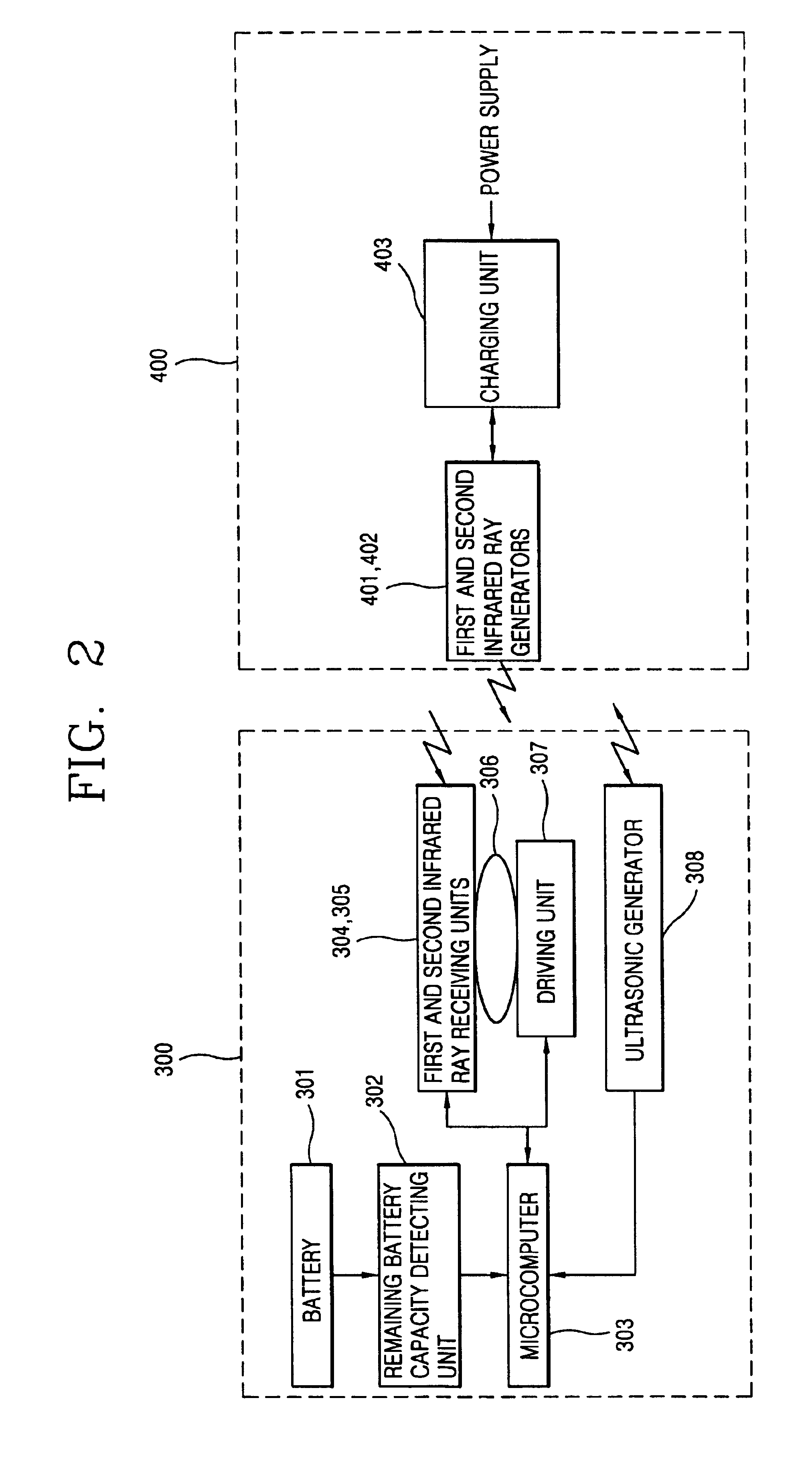
An automatic charging system and method of a robot cleaner of the present invention is featured in that a few infrared ray sensors are installed at a robot cleaner and rotated to accurately and quickly detect an infrared signal received from a fixedly installed charging unit, so that the robot cleaner can be accurately and quickly moved to the charging unit, a power terminal of the robot cleaner can be accurately and quickly connected to a charge terminal of the charging unit, and a cost for implementing the robot cleaner can be reduced.

A preferred embodiment of the present invention will now be described with reference to FIGS. 2 to 4.

The automatic charging system and method of a robot cleaner of the present invention may be installed at a toy or any device which is movable by using a battery.

FIG. 2 is a schematic block diagram s...


PUM


Abstract

An automatic charging system of a robot cleaner includes: a rotating plate installed at a robot cleaner; an infrared ray receiving unit mounted at the rotating plate and receiving an infrared signal generated from a power supply unit while being rotated; a microcomputer for moving the robot cleaner to the power supply unit on the basis of the received infrared signal; and an ultrasonic generator for generating a stop signal when the robot cleaner nears to the power supply unit. A robot cleaner can be accurately and quickly moved to a power supply unit for a rapid charging operation, and a cost for implementing the robot cleaner can be reduced.

Description

BACKGROUND OF THE INVENTION1. Field of the InventionThe present invention relates to a robot cleaner and, more particularly, to an automatic charging system and method of a robot cleaner.2. Description of the Background ArtFIG. 1 is a schematic block diagram showing a construction of a charging system of a robot cleaner in accordance with a conventional art.As shown in FIG. 1, a charging system of a robot cleaner (not shown) consists of a power receiving unit 100 of a robot cleaner and a power supply unit 200 for charging a battery 101 of the robot cleaner.The power supply unit 200 includes an infrared ray sensor 201 for communicating with the robot cleaner and a charging unit 202 for charging the battery 101 of the robot cleaner. The infrared ray sensor 201 is installed at the charging unit 202 and generates an infrared signal in a predetermined direction.The power receiving unit 100 of the robot cleaner includes: a battery 101; a remaining battery capacity detector 102 for detecti...

Claims


Application Information

Patent Timeline
IPC IPC(8): A47L9/28A47L9/00G05D1/02
CPCA47L9/009A47L9/2805A47L9/2852A47L9/2873A47L9/2878G05D1/0225G05D1/0242G05D1/0255A47L9/2894A47L2201/022G05D2201/0203A47L9/28
Inventor JEON, HYEONG-SHINWOO, CHUN-KYU
Owner LG ELECTRONICS INC
Why Eureka
Try Eureka