Eureka AIR delivers breakthrough ideas for toughest innovation challenges, trusted by R&D personnel around the world.

Grip friction pattern

a friction pattern and grip technology, applied in the field of grip friction patterns, can solve the problems of not describing a pattern utilizing a combination, and achieve the effect of reducing the discomfort associated with gripping patterns, effective and comfortable, and positive gripping surfaces

Inactive Publication Date: 2005-03-01
CHRISTIANSEN NED F
View PDF22 Cites 68 Cited by
  • Summary
  • Abstract
  • Description
  • Claims
  • Application Information

AI Technical Summary

Benefits of technology

In view of the foregoing disadvantages inherent in the known types of friction patterns, this invention provides an improved friction pattern that is both effective and comfortable. As such, the present invention's general purpose is to provide a new and improved friction pattern that will provide a positive gripping surface while simultaneously diminishing the discomfort associated with pointed friction patterns
The pattern works by providing space between the frusto-conical projections, allowing for a user's hand to “fill-in” the gaps, and a pint with each pyramid, providing a higher coefficient of friction. Together, the pattern provides a better grip, without catching the user's hand, a problem associated with a pointed surface.

Problems solved by technology

While the aforementioned inventions accomplish their individual objectives, they do not describe a pattern that utilizes two distinct shapes in a fractioning pattern.
They also do not describe a pattern utilizing a combination of flat and pointed shapes.

Method used


Image

  • Grip friction pattern
  • Grip friction pattern
  • Grip friction pattern

Examples


Embodiment Construction

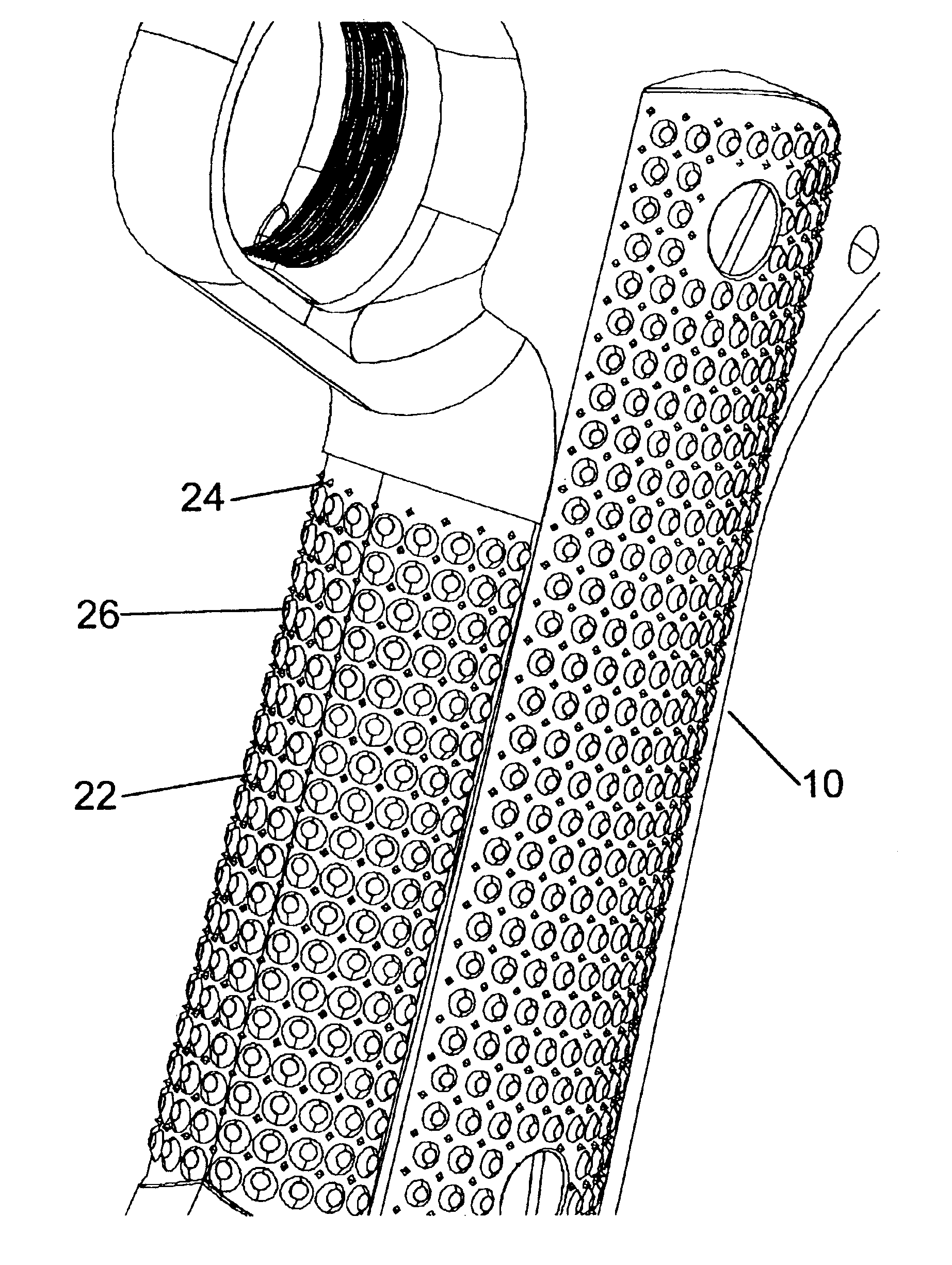
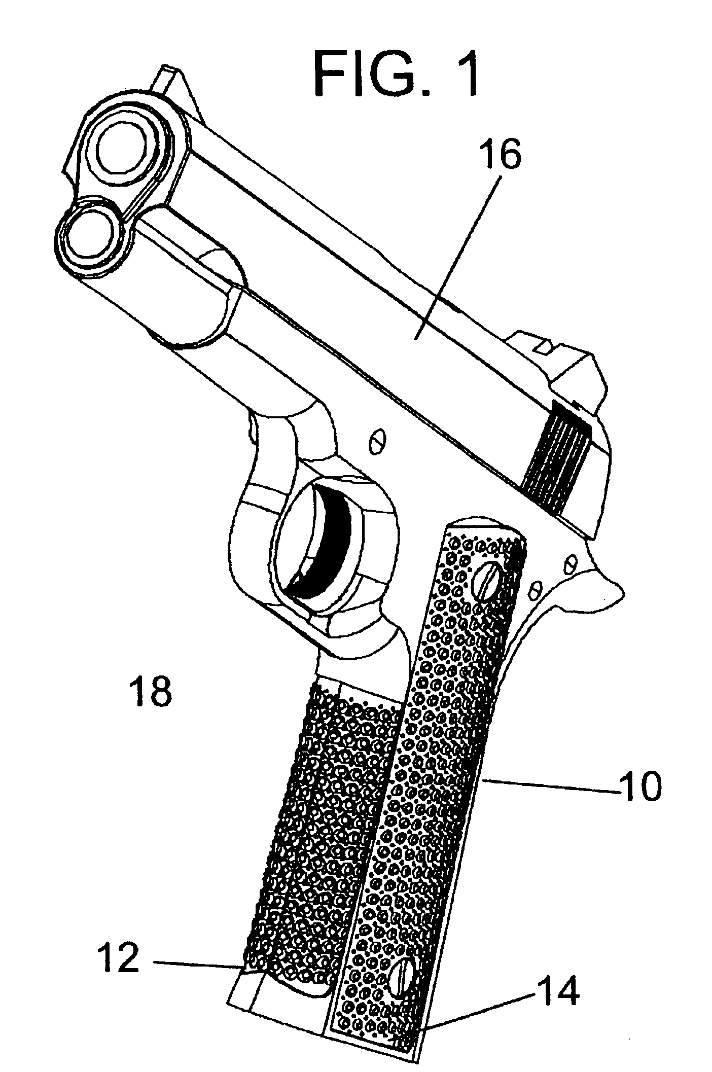
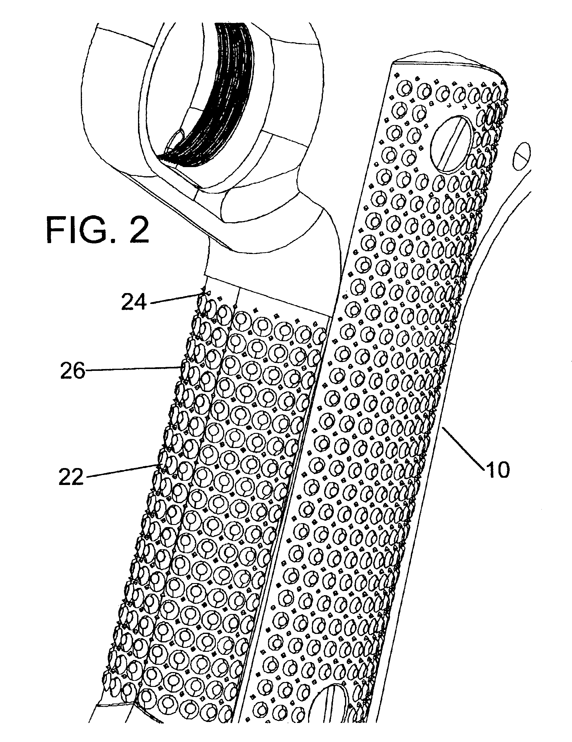
With reference now to the drawings, the preferred embodiment of the friction pattern is herein described. Referring to FIG. 1, the pattern 10 is applied to any surface that is to be grasped. In this case pattern 10 is applied to the fore strap 12 and side panels 14 of a handgun's 16 grip 18, thought the pattern may be used on any surface on any object that is to be grasped. In its preferred embodiment, shown in FIG. 2 the pattern consists of a regularly repeated pattern of frusto-conical projections 22 and pyramidical projections 24. The pyramidical projections 24 may have a base of any shape, such as a circle, triangle, square, and so forth. The drawings should not be seen as limiting on this feature. Preferably, the pyramidical projections 24 will be a four-sided pyramid, with a square base. Ideally, the pattern should alternate one frusto-conical projection 22 and one pyramidical projection 24, however, random patterns would also provide an improved friction surface. Because of t...


PUM


Abstract

The present invention discloses a grip fractioning pattern for any object, but specifically designed for handgun and rifle grips. The pattern consists of a series of spaces frusto-conical projections regularly spaced about the surface of the weapon's grip. Alternatively, the series may be interrupted by an interspaced series of pyramids, with their points not extending above the height of the frusto-conical projections. The grip pattern may be utilized in any circumstance where a user desires greater and more comfortable friction when gripping an object.

Description

FIELD OF INVENTIONThe present invention relates to friction patterns for firearm and other grips and more specifically relates to the use of spaced apart projections of a combination of shapes to provide friction for gripping a firearm grip. The pattern may be used in any circumstance where increased friction would be desired to achieve a comfortable hold on an object with a hand.BACKGROUND OF THE INVENTIONThe addition of friction, or fractioning, patterns to a grip surface is known in the prior art. Their basic function is to disrupt any uniformity in the grip surface to increase friction and provide a better interface between a hand (or other holding apparatus) and the grip surface. Often times, as in the case of robotics, a grasping apparatus is employed and that grasping apparatus has a friction pattern. One common field in which friction patterns are employed is weapon grips. For example, U.S. Pat No. 5,615,505 to Vaid (1997); U.S. Pat. No. 5,557,872 to Langner (1996); U.S. Pat...

Claims


Application Information

Patent Timeline
IPC IPC(8): F41C23/10F41C23/00
CPCF41C23/10
Inventor CHRISTIANSEN, NED F.
Owner CHRISTIANSEN NED F
Why Eureka
Eureka Blog
Learn More