
Combination lock with dial displaying window

a dial matching and combination lock technology, applied in padlocks, building locks, constructions, etc., can solve the problems of deteriorating identification functions, drawbacks, and inability to idealize the dial matching indication unit for the combination lock, and achieve the effect of quick and accurate identification and easy deterioration

Inactive Publication Date: 2005-03-01
LING RENNY TSE HAW
View PDF12 Cites 19 Cited by
  • Summary
  • Abstract
  • Description
  • Claims
  • Application Information

AI Technical Summary

Benefits of technology

A primary objective of this invention is to overcome the above drawbacks and provide a dial matching indication device for a combination lock to clearly mark the reference position for matching the dials, such that the user may quickly and accurately identify the combination of a series of numerals (or symbols) of the dials through the dial matching indication device for unlocking the combination lock. In addition, the dial matching identification function provided by the device of this invention will not be easily deteriorated by the usage of the lock.
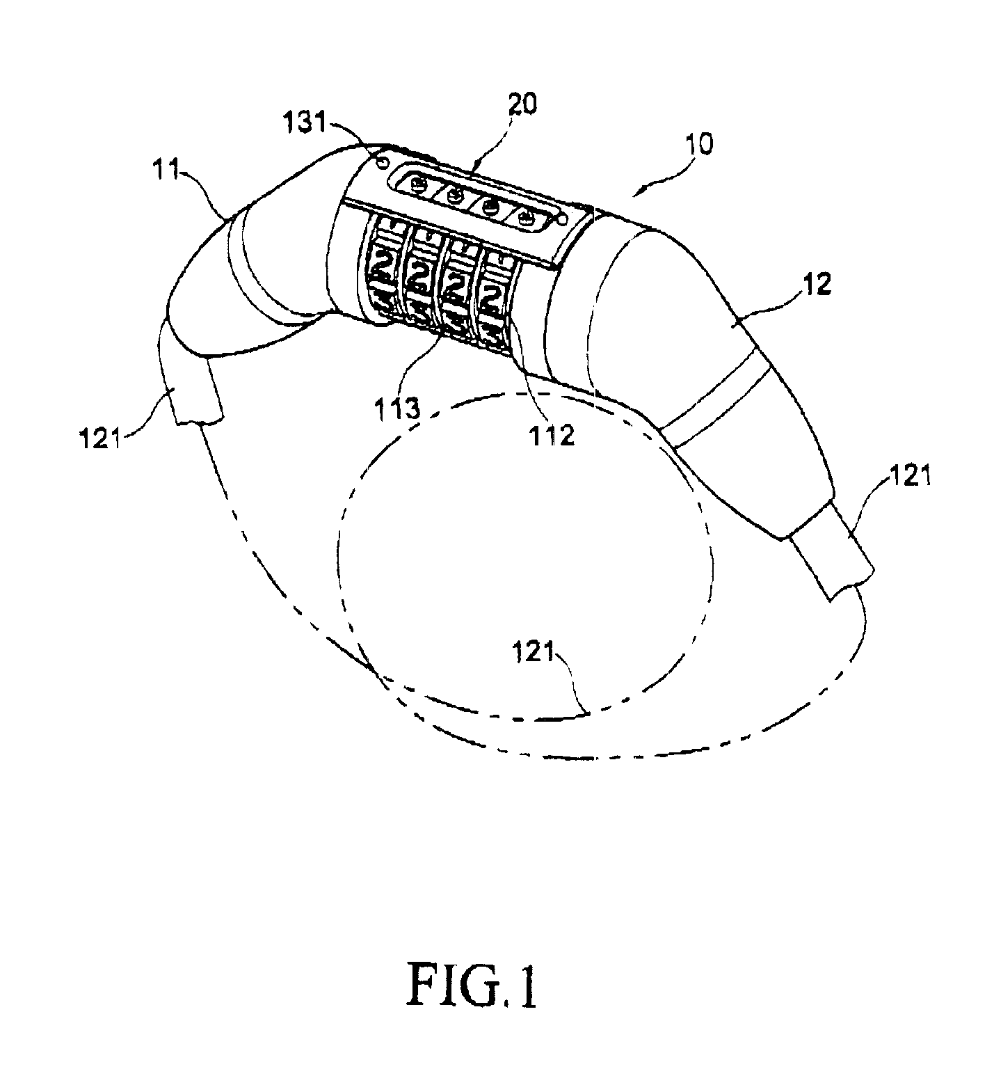
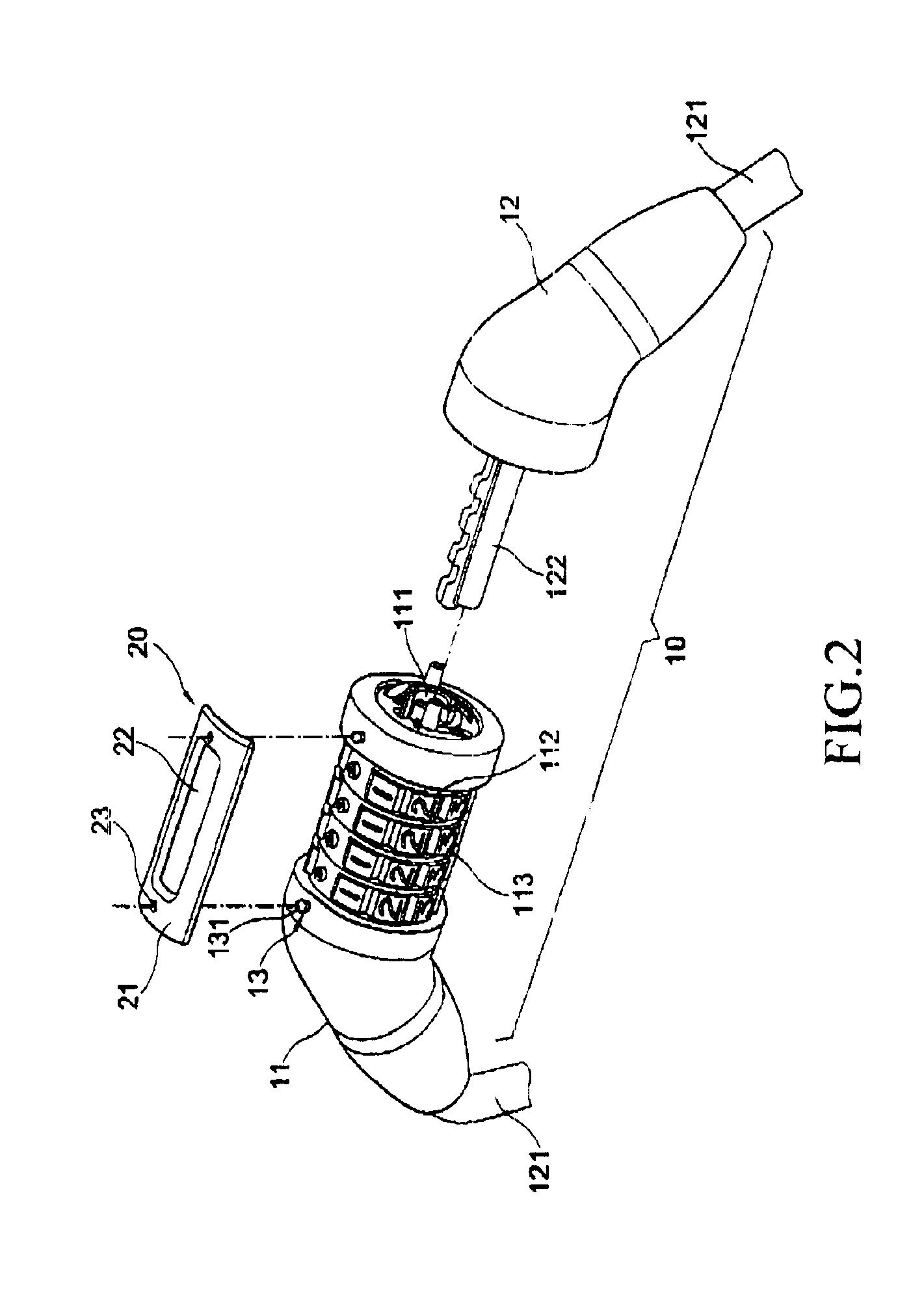
According to the above objective, this invention provides a window-type dial matching identification mechanism, comprising a dial matching frame which is provided on a lock mechanism. The frame has at least one window placed across all the dials at a predetermined matching position, so that the user can quickly and accurately identify the combination of the dials through the window for unlocking the lock.

Problems solved by technology

However, such a dial matching indication unit is not an ideal solution for the combination lock.
Usually, the dial matching indication unit is not very apparent to the user and thus, some drawbacks may occur.
For example:1. When the grooves or protrusions are used on the surface of the combination lock as the dial matching indication unit, if the depth or height thereof is too small, the visual effect for identification may not be significant enough; on the other hand, if the depth of the grooves is too large, dust may be accumulated therein; if the height of the protrusions is too large, they may appear awkward.2. If the dial matching indication unit is printed on the surface of the lock or in the form of a sticker, they are easily damaged during the usage of the lock and may become unclear or even disappear and thus, the identification function thereof is deteriorated.3. Even if a user knows that the designated combination number of the dials must exactly match with the indication unit in order to unlock the locks, combination locks usually allow a minute amount of displacement such that the locks still cannot be unlocked even if the indicating unit has pointed to the side edges of the designated combination number with excessive displacement.

Method used


Image

  • Combination lock with dial displaying window
  • Combination lock with dial displaying window
  • Combination lock with dial displaying window

Examples


Embodiment Construction

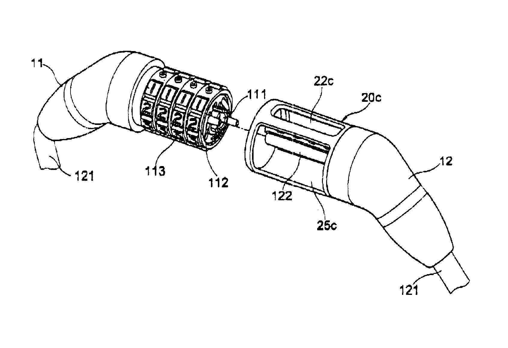
FIG. 1 shows a combination lock 10 with a dial matching frame 20 thereon such that the user can clearly identify the combination of the dials for unlocking the lock. As illustrated in the figures, the combination lock 10 includes a lock body 11 and a latch 12, wherein the lock body 11 further has a locking hole 111 and a plurality of parallel dials 112 provided around the exterior of the lock body 11. Each of the dials 112 can be Independently rotated with respect to the lock body 11 and is provided with numerals 113 (or symbols) surrounding the surface thereof. When each of the dials 112 is rotated to a preset combination at the predetermined dial matching position, the lock body 11 may be unlocked. Otherwise, when one or more numerals 113 of the dials 112 at the matching position do not match with the preset combination, the lock body 11 remains at the locked state. The application of this kind of combination lock 10 is well known to the persons skilled in the art and thus, the de...


PUM


Abstract

A combination lock with a dial displaying window which is directed to a combination lock with the installation of a dial matching frame placed across all the dials and having at least one window for the users to check the combination numerals or symbols on the dials through the window for unlocking the combination lock. The dial matching frame may be differently constructed to provide the window with the displaying function. A magnification lens may be mounted on the window to further enhance the effectiveness during utilization.

Description

BACKGROUND OF THE INVENTION1. Field of the InventionThis invention is related to a dial matching device for a combination lock, in particular, a dial matching device that helps the user to more accurately identify the corresponding locations of all the dials for unlocking the combination lock,2. Description of the Related ArtA combination lock is a locking apparatus utilizing dials which must be adjusted to the pre-designated locations of preset numerals or symbols for unlocking the combination lock.The conventional combination lock usually includes indication arrows, symbols, grooves or protrusions as the dial matching device, which is referred to as “dial matching indication unit” hereinafter, on one or both sides of the parallel dials of the combination lock to identify the locations for matching the dials with the combination. The user adjusts the dials of the combination lock to the locations for matching the dials with the preset combination with reference to the dial matching...

Claims


Application Information

Patent Timeline
Patent Type & Authority Patents(United States)
IPC IPC(8): E05B37/02E05B37/00
CPCE05B37/025Y10T70/7305Y10T70/7407Y10T70/7435Y10T70/435Y10T70/8405Y10T70/487Y10T70/489Y10T70/7412
Inventor LING, RENNY TSE-HAW
Owner LING RENNY TSE HAW
Learn More