Impact machine

a technology of impact machine and impact plate, which is applied in the direction of manufacturing tools, forging/pressing/hammering apparatus, forging hammers, etc., can solve the problem of more difficult to make the die resilien

Inactive Publication Date: 2005-03-08
MORPHIC TECH
View PDF10 Cites 14 Cited by
  • Summary
  • Abstract
  • Description
  • Claims
  • Application Information

AI Technical Summary

Problems solved by technology

This makes it more difficult to make the die resilient.

Method used


Image

  • Impact machine
  • Impact machine
  • Impact machine

Examples


Embodiment Construction

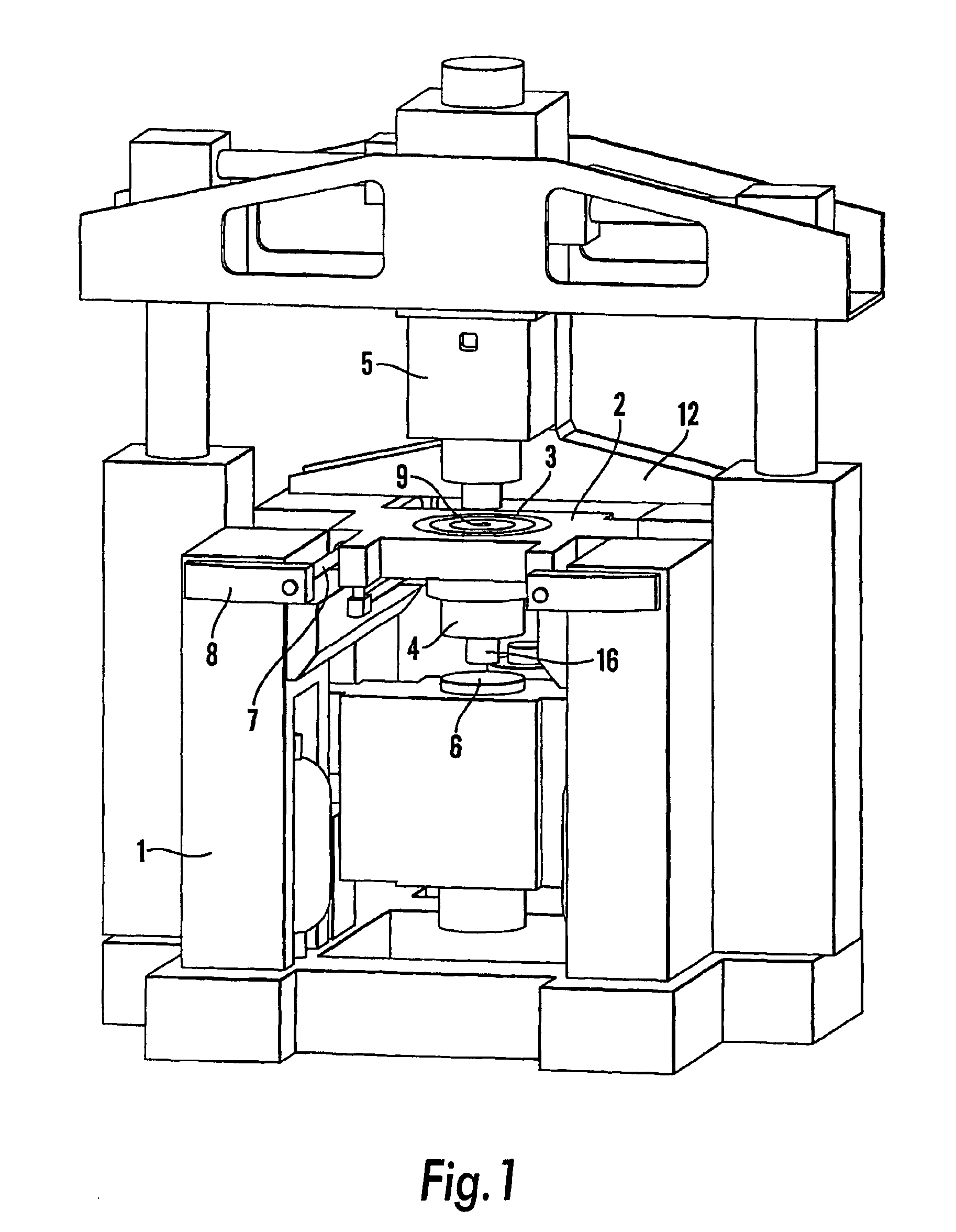
In FIG. 1 there is shown a so called impact machine. This is a machine for working by employing a high kinetic energy for in the first place metal working, such as cutting an punching, forming of metals, powder compaction and similar operations. In the described example it is conceived that the machine shall be used for compacting metal powders.

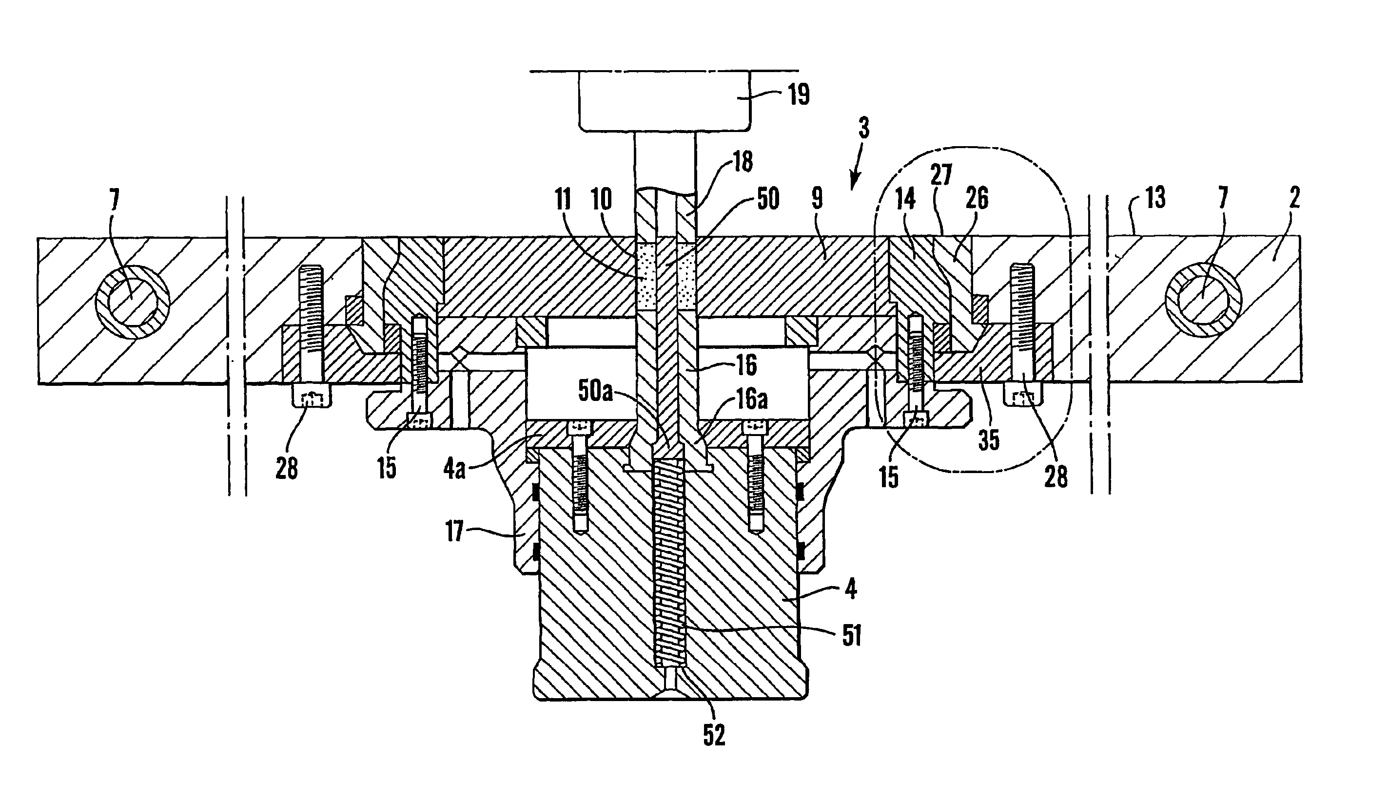
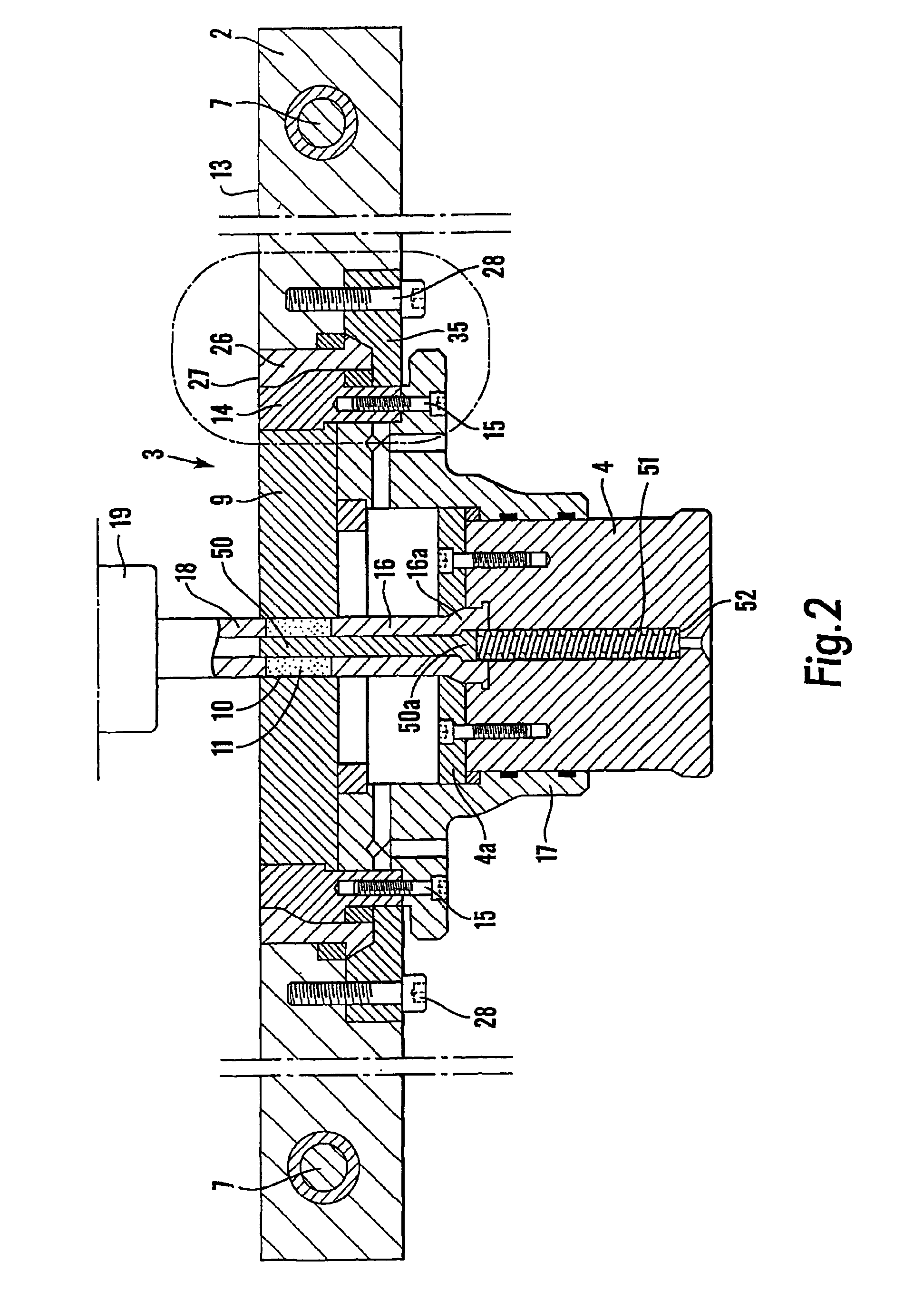
The machine comprises a stand 1 and a tool carrier 2, which carries a tool unit 3. The tool unit 3 comprises a die 9 and a lower punch 16 having a lower punch holder 4 and a lower punch holder guide 17, provided under the die. The working principle of the machine is the development of a very high kinetic energy of short duration of an upper ram 5 and of a lower ram 6, which simultaneously are stricken form above and from below, respectively, against an upper punch 18 and against the lower punch 16 in the tool unit 3 and against the working material 11 which is placed in the mould cavity 10, FIG. 2, of the tool die, said working material consi...


PUM

PropertyMeasurementUnit
impact energyaaaaaaaaaa
velocitiesaaaaaaaaaa
friction forcesaaaaaaaaaa

Abstract

The invention concerns an impact machine for forming, cutting, or punching a working material in a mould die by impact action during an impact operation carried out by means of impact devices, preferably from two opposite directions, said impact devices being provided to strike the working material or impact members which transfer the impact energy of the impact devices to the working material, said die (9) being carried by a carrier (2) included in the impact machine. According to the invention, the die is resiliently mounted in the carrier, which e.g. may consist of a stationary or moveable table.

Description

TECHNICAL FIELDThe present invention relates to an impact machine for forming, cutting, or punching a working material in a mould die by impact action during an impact operation carried out by means of impact devices, preferably from two opposite directions, said impact devices being provided to strike the working material or impact members which transfer the impact energy of the impact devices to the working material, said die being carried by a carrier included in the impact machine. The invention also relates to said carrier and how the die i mounted in the carrier.BACKGROUND OF THE INVENTIONIf the impact devices of an impact machine of the above mentioned type, where the impact devices move towards the working material from two opposite directions, simultaneously hit the working material or members which transfer the kinetic energy of the impact device to the working material, and if the moveable impact devices which move towards one another, have equally large momentums, e.g. e...

Claims


Application Information

Patent Timeline
Patent Type & Authority Patents(United States)
IPC IPC(8): B21J7/34B21J7/00
CPCB21J7/34
Inventor OLSSON, H.ANG.KAN
Owner MORPHIC TECH
Why Eureka
Try Eureka