Rotary manipulation type input device and electronic apparatus using the same

a technology of input device and rotary click, which is applied in the direction of snap-action arrangement, pulse technique, instruments, etc., can solve the problem of difficulty in synchronizing between rotary click feeling and signal outpu

Inactive Publication Date: 2005-03-08
PANASONIC CORP
View PDF6 Cites 43 Cited by
  • Summary
  • Abstract
  • Description
  • Claims
  • Application Information

AI Technical Summary

Problems solved by technology

It was hence difficult to synchronize bet...

Method used


Image

  • Rotary manipulation type input device and electronic apparatus using the same
  • Rotary manipulation type input device and electronic apparatus using the same
  • Rotary manipulation type input device and electronic apparatus using the same

Examples


embodiment

(Embodiment)

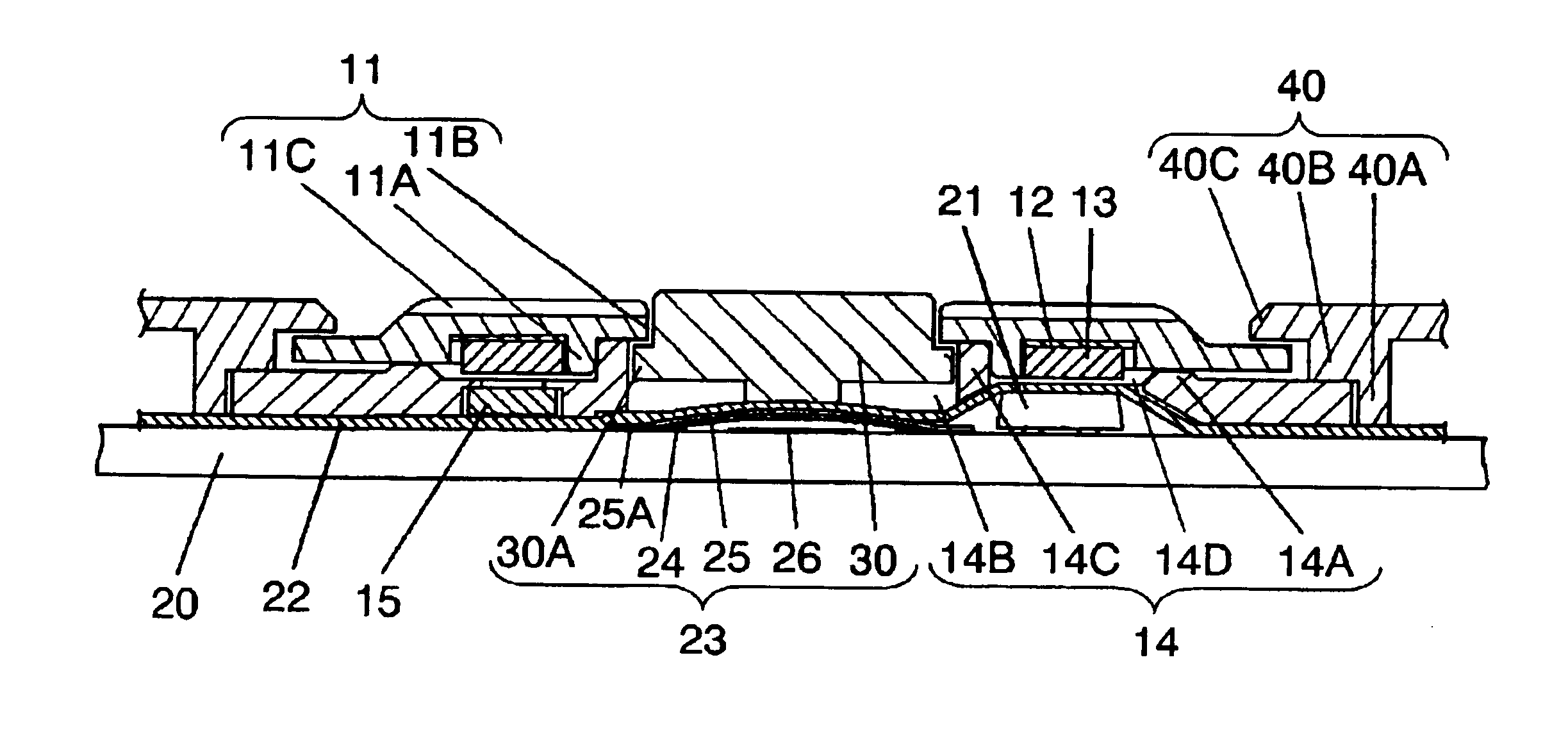
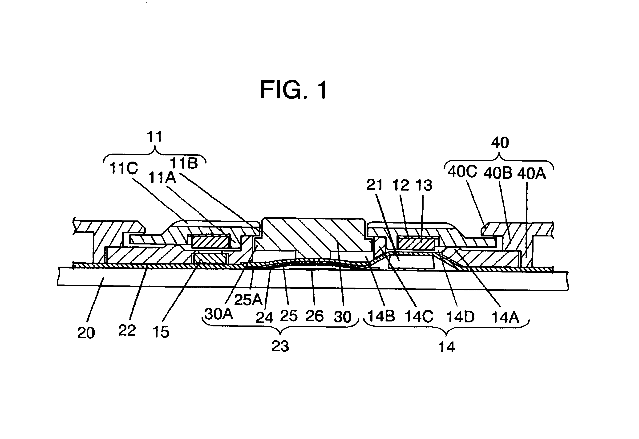
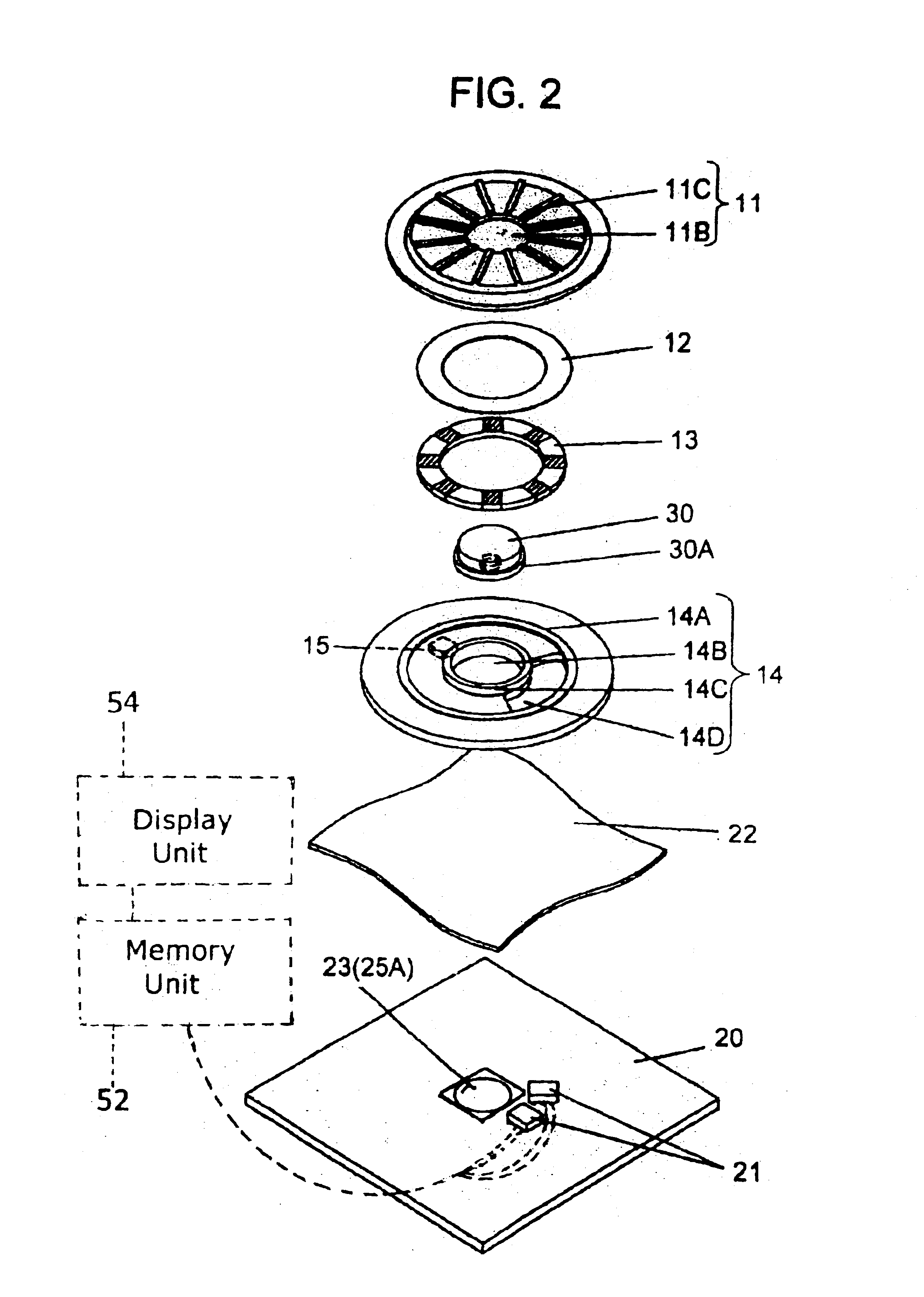
FIG. 1 is a sectional view of a rotary manipulation type input device in an embodiment of the invention, and FIG. 2 is its perspective exploded view. In FIG. 1 and FIG. 2, an operating element 11 is made of resin, and is formed substantially in a circular ring. At its lower side, a magnetic plate 12 made of silicon steel or magnetic stainless steel similarly processing in a ring form is disposed, and a ring-shaped magnet 13 is overlaid concentrically beneath it.

The magnetic plate 12 and ring-shaped magnet 13 are integrally fixed to the operating element 11 precisely by insert forming process.

The ring-shaped magnet 13 has its N poles and S poles magnetized at specified angle alternately or in the same polarity only.

In FIG. 2, for the ease of understanding, the magnetized portion of the ring-shaped magnet 13 is indicated by shaded area.

The ring-shaped magnet 13 is composed of individual magnets linked by means of resin to form a ring shape, or is formed in a C-shape in a t...


PUM


Abstract

A rotary manipulation type input device obtains a specified output by detecting intensity changes of magnetic field due to rotation of an operating element by a detecting element disposed on a substrate beneath a base, using a ring-shaped magnet disposed at the lower side of the operating element disposed rotatably on the base. By rotary manipulation of the operating element, an attractive and repulsive force is generated between the ring-shaped magnetic and the magnetic disposed on the base, so that an operation contact click-feeling is obtained, and therefore the rotary click-feeling and signal output can be synchronized easily, and deterioration of rotary click-feeling is very rare.

Description

FIELD OF THE INVENTIONThe present invention relates to a rotary manipulation type input device for telephone directory retrieval or various input operations, and an electronic apparatus using the same.BACKGROUND OF THE INVENTIONA rotary manipulation type input device of magnetic system is used for selecting and setting operations of various items displayed on a screen such as character inputs in an electronic apparatus.Such conventional rotary manipulation type input device is explained below while referring to FIG. 4 and FIG. 5.FIG. 4 is a sectional view of rotary manipulation type input device of magnetic system in a prior art, and FIG. 5 shows a rotary manipulation click-feeling generating mechanism which is one of the essential parts thereof. In FIG. 4 and FIG. 5, a substrate 101 is a flat plate, which is located in the bottom of the rotary manipulation type input device. A box-shaped case 102 opened downward is coupled above the substrate 101.A dent 101A is formed in the middle...

Claims


Application Information

Patent Timeline
IPC IPC(8): H01H5/00H01H5/02H03K17/94H03K17/97H01H25/06H01H25/00G06F3/0338H01H19/11H01H19/20H01H36/00H01H89/00
CPCH01H5/02H01H25/065H03K17/97H03K2217/94068H01H2019/006H01H2003/506G06F3/0338H01H19/11H01H19/20
Inventor YOKOJI, SHIGERUYAMAMOTO, TAMOTSU
Owner PANASONIC CORP
Why Eureka
Try Eureka