Capacitive microsystem for recording mechanical deformations, use and operating method

a microsystem and mechanical deformation technology, applied in the direction of instruments, pedestrian/occupant safety arrangements, force/torque/work measurement apparatus, etc., can solve the problems of limiting the possibility of cost reduction, affecting the stability and overload resistance of strain gages, and affecting the stability of strain gages long-term

Inactive Publication Date: 2005-03-15
SIEMENS AG
View PDF21 Cites 13 Cited by
  • Summary
  • Abstract
  • Description
  • Claims
  • Application Information

AI Technical Summary

Problems solved by technology

However, the adhesive attachment and contacting of strain gages proves to be technologically difficult.
This is disadvantageous in particular in the case of mass production and applications in the field.
Furthermore, the long-term stability and overload resistance of strain gages are not satisfactory.
This limits the possibility for cost reduction.

Method used


Image

  • Capacitive microsystem for recording mechanical deformations, use and operating method
  • Capacitive microsystem for recording mechanical deformations, use and operating method
  • Capacitive microsystem for recording mechanical deformations, use and operating method

Examples


Embodiment Construction

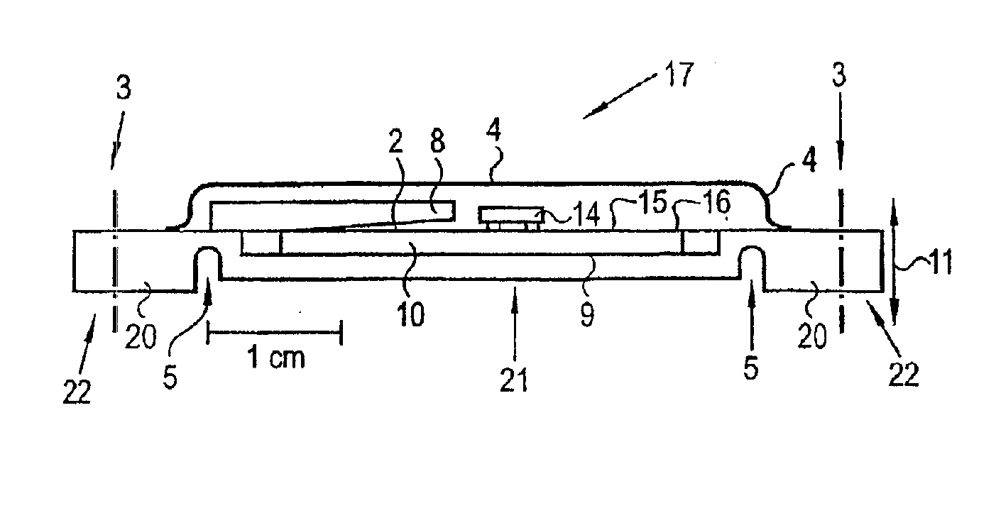
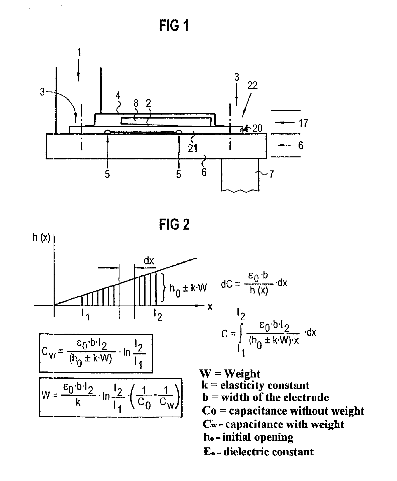
FIG. 1 shows a sectioned side view of a capacitive microsystem 17, which is mounted on a deforming element 6. The deforming element 6 is in turn fastened to a support 7 and is loaded on the opposite side by the force of a weight 1. At the fastening points 3, the capacitive microsystem or measuring system 17 is rigidly connected to the deforming element 6. As a result, the bending element 20 of the capacitive microsystem 17 will respond to movements, in particular flexures, of the deforming element 6 under loading by replicating them in a defined way. As a result, there is a fixed relationship between the capacitive microsystem 17 and the deforming element 6. In the capacitive microsystem 17, the end region 22 of the support 21 lying on the right in FIG. 1 remains static, since it is rigidly connected to the deforming element 6 at the fastening point 3. In its central region between the bending regions 5, the support 21 will undergo a deflection which correlates with the deformation ...


PUM

PropertyMeasurementUnit
mechanical deformationsaaaaaaaaaa
capacitanceaaaaaaaaaa
energyaaaaaaaaaa

Abstract

The invention relates to a capacitive microsystem, which can be used to replace conventional strain gauges used currently. The microsystem has substantial advantages with regard to handling, overload stability and endurance. Capacitive microsystems of this type can be used to record deformations and to calculate forces, torque etc. They can be used in particular to determine the weight of vehicle seats, to provide for example deployment data for an airbag.

Description

TECHNICAL FIELD OF THE INVENTIONThe invention relates to a capacitive microsystem for recording mechanical deformations, to the use thereof for measuring forces and to an operating method.BACKGROUND OF THE INVENTIONVarious capacitive torque and force sensors are known in the prior art. In the industrial sector, torques are today generally measured with measuring cells which are fitted with strain gages. Strain gages are attached directly to the measuring point on a structural element. However, the adhesive attachment and contacting of strain gages proves to be technologically difficult. This is disadvantageous in particular in the case of mass production and applications in the field. Furthermore, the long-term stability and overload resistance of strain gages are not satisfactory.Other known capacitive torque and force sensors have, for example, electrode structures that engage in one another in a comb-shaped manner. The displacements occurring in these cases are only a few microme...

Claims


Application Information

Patent Timeline
Patent Type & Authority Patents(United States)
IPC IPC(8): B60N2/00B60R21/01G01G19/414G01G19/40G01G7/00G01G7/06G01L1/14B60R21/015
CPCB60N2/002G01G7/06B60R21/0152G01L1/142B60R21/01516G01G19/4142
Inventor DOEMENS, GUENTERSPRIEGEL, DIETERWUENSCHE, HANS
Owner SIEMENS AG
Why Eureka
Try Eureka