Mechanically opened ball seat and expandable ball seat

a technology of ball seat and ball seat, which is applied in the direction of fluid removal, borehole/well accessories, construction, etc., can solve the problems of limiting the size of subsequent equipment, and affecting the operation of the next equipmen

Inactive Publication Date: 2005-03-15
WEATHERFORD TECH HLDG LLC
View PDF21 Cites 123 Cited by
  • Summary
  • Abstract
  • Description
  • Claims
  • Application Information

AI Technical Summary

Problems solved by technology

However, this leaves the ball and ball seat in the well bore, potentially causing problems for subsequent operations.
This potentially limits the size of subsequent equipment that can pass freely through the ball seat and further downhole without the risk of damage or obstruction.
Internal pressures can become quite high when breaking circulation or circulating a liner through a tight section.
Therefore, releasing or opening a ball seat by increased pressure can cause the ball to pass through the drill pipe at a relatively high velocity and prematurely release ball seats or shift sleeves located downhole.
The large surge pressure created by the ball seat's release can also undesirably damage formations or cause hydraulic tools below the ball seat to actuate prematurely.
Even with precision manufacturing and extensive quality control, occasional malfunctions occur in the activation mechanisms of the tool and the release or opening mechanisms

Method used


Image

  • Mechanically opened ball seat and expandable ball seat
  • Mechanically opened ball seat and expandable ball seat
  • Mechanically opened ball seat and expandable ball seat

Examples


Embodiment Construction

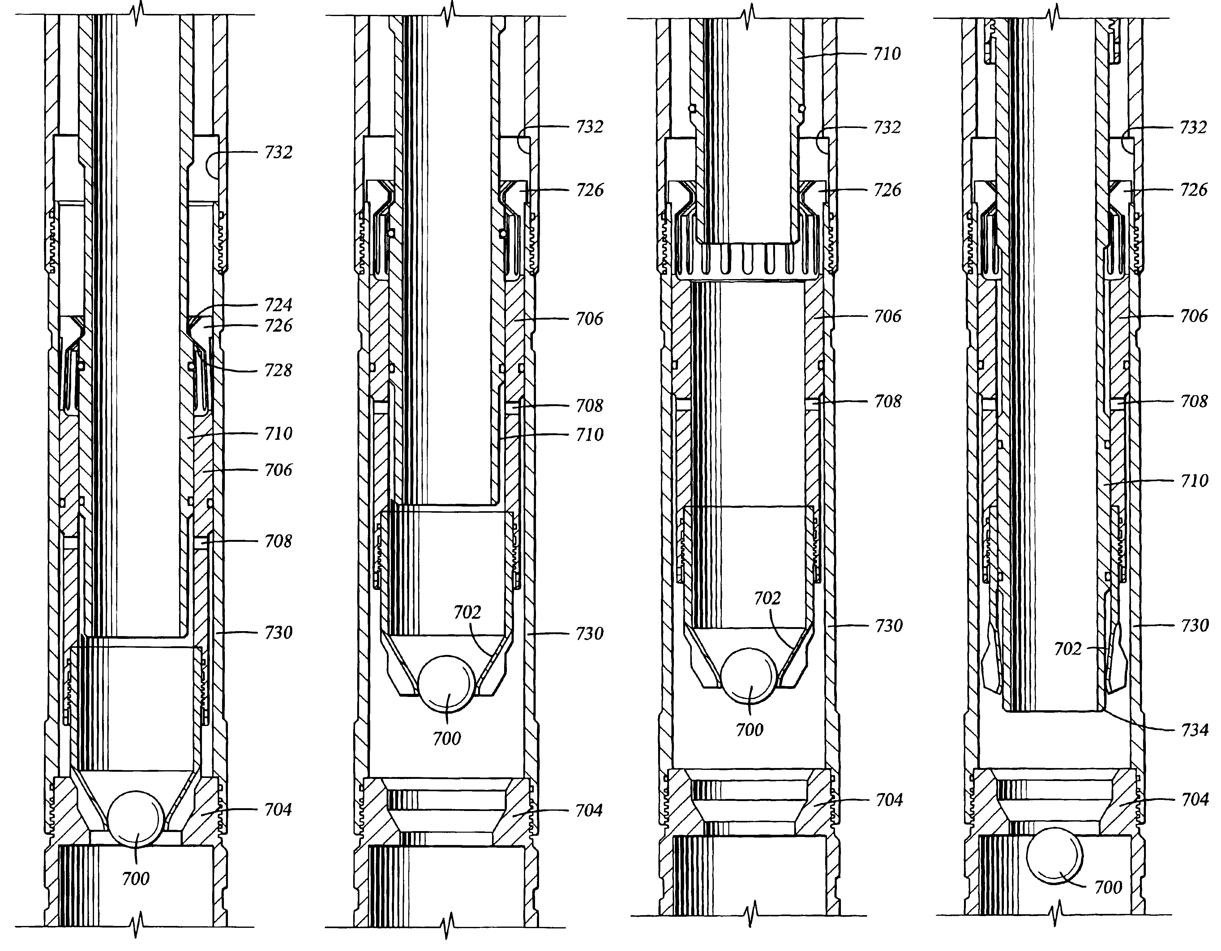
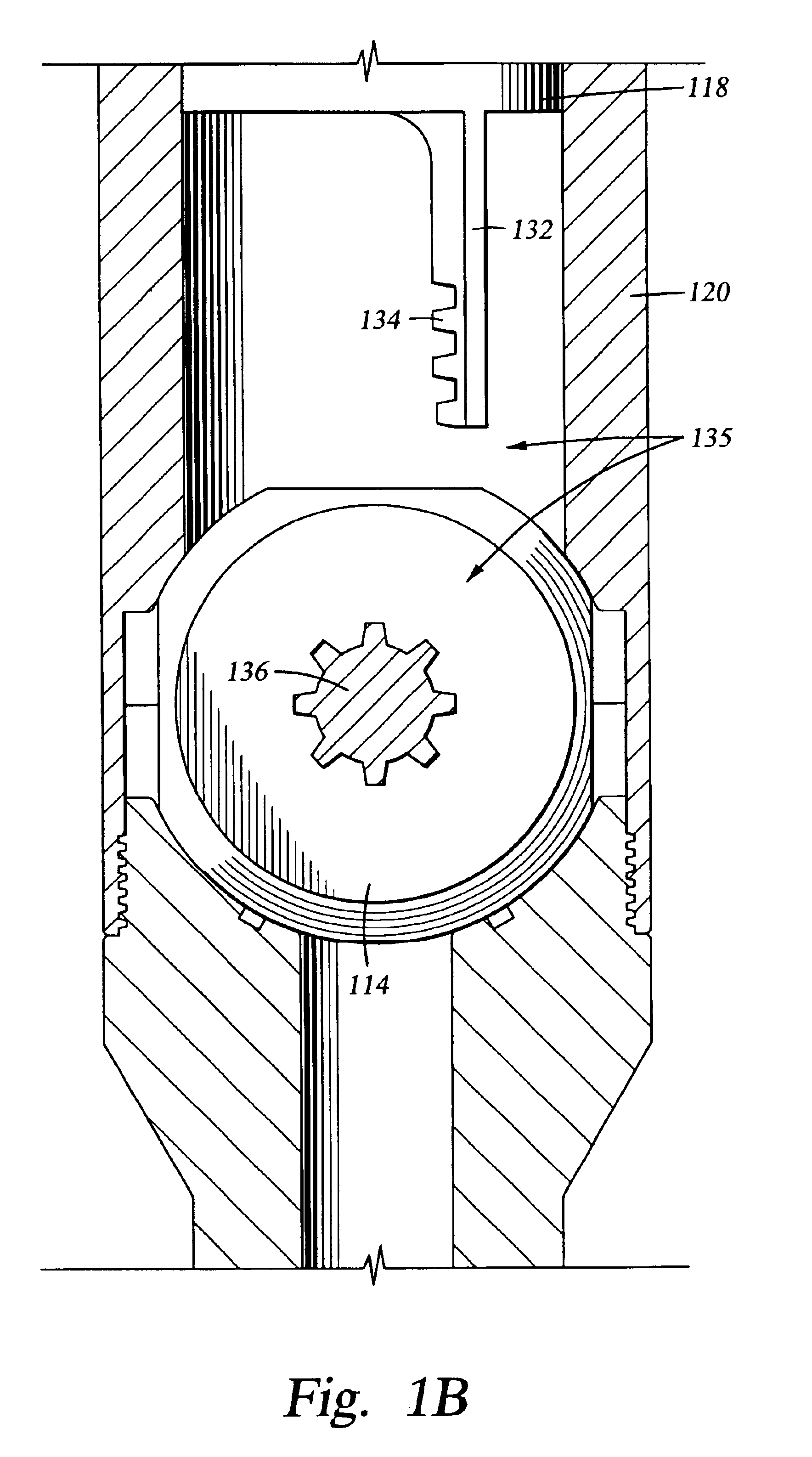
The present invention generally relates to an apparatus and method for temporarily sealing a fluid flow conduit within a wellbore in order to operate hydraulic tools therein. FIG. 1A illustrates an embodiment of the present invention as it would appear positioned inside a liner 100 within a wellbore 102. Visible in FIG. 1A is a telescoping sleeve 104 held within a sub 106 that is connected to a work string 108, an expandable c-ring 110 that circumscribes the sub, a biasing member 112 that acts on the telescoping sleeve, a multiposition valve 114 with a ball seat 116, and a slideable inner sleeve 118 positioned inside an outer member 120. The axial position of the outer member is fixed relative to the liner 100. FIG. 1C provides a cross section view of the tool shown in FIG. 1A as it would appear rotated ninety degrees. An enlarged view of one embodiment of the multiposition valve as seen from the angle displayed in FIG. 1A is visible in FIG. 1B. Axial movement of the work string 108...


PUM


Abstract

A method and apparatus for obstructing the passage of fluid within a fluid flow conduit and subsequently reconfiguring the tool to allow substantially full-bore passage therethrough. Pressure developed upstream of the obstruction can be utilized to operate pressure actuated tools such as liner hangers. Equipment used in subsequent wellbore operations such as drill pipe darts can pass undamaged through the opened port. In an embodiment, the flow through a tubular is obstructed by placing a ball on an expandable ball seat, developing a pressure differential across the ball seat, equalizing the pressure after the hydraulically actuated tool completes its function, and mechanically manipulating the drill string to open the expandable ball seat and allow the ball to pass through.

Description

BACKGROUND OF THE INVENTION1. Field of the InventionEmbodiments of the present invention generally relate to methods and apparatus to sealably close and open a tubular within an oil and gas wellbore. More particularly, embodiments of the present invention generally relate to methods and apparatus for creating a fluid seal used to produce a pressure differential that is utilized to actuate a hydraulic tool downhole.2. Description of the Related ArtHydrocarbon wells typically begin by drilling a borehole from the earth's surface to a selected depth in order to intersect a hydrocarbon-bearing formation. Steel casing lines the borehole formed in the earth during the drilling process. This creates an annular area between the casing and the borehole that is filled with cement to further support and form the wellbore. Thereafter, the borehole is drilled to a greater depth using a smaller diameter drill than the diameter of the surface casing. A liner may be suspended adjacent the lower end...

Claims


Application Information

Patent Timeline
IPC IPC(8): E21B34/00E21B34/06E21B34/12E21B34/10
CPCE21B34/06E21B34/12E21B34/102E21B2034/002E21B2200/04E21B23/04E21B34/00E21B34/14
Inventor GUDMESTAD, TARALDHIRTH, DAVID E.PEDERSEN, GERALD D.
Owner WEATHERFORD TECH HLDG LLC
Why Eureka
Try Eureka