Head protecting airbag device

a technology for protecting airbags and head, which is applied in the direction of pedestrian/occupant safety arrangements, vehicular safety arrangments, vehicle components, etc., can solve the problems of affecting the safety of passengers, the airbag may not be able to expand smoothly along the guide member, etc., and achieves the effect of smooth expansion and inflated

Inactive Publication Date: 2005-03-15
TOYODA GOSEI CO LTD
View PDF10 Cites 41 Cited by
  • Summary
  • Abstract
  • Description
  • Claims
  • Application Information

AI Technical Summary

Benefits of technology

With this construction, when the airbag expands, the pillar garnish covering the vehicular interior side of the pillar portion opens at its window-side edge toward the vehicular interior to allow the connection member to slide downward. Moreover, the airbag is usually constructed such that the portion for covering the vehicular interior side of the window is larger than the portion for covering the vehicular interior side of the pillar garnish. Therefore, the lower edge of the airbag tends to be pulled toward the window side, creating tension. Even if the airbag is tensed toward the window while it is being expanded, however, in the aforementioned construction the connection member can slide smoothly downward along the guide member. This is because the guide member has no interference with the edge of the pillar garnish that is opened. As a result, the airbag body can be smoothly expanded and inflated.

Problems solved by technology

However, the head protecting airbag device having the aforementioned construction is not so constructed that the airbag expanded and inflated covers substantially the whole face of the vehicular interior side of the center pillar portion.
In the head protecting airbag device thus constructed, however, in case the opening is not smoothly formed when the airbag expands and inflates, the downward movement of the connection member is obstructed, and the airbag may be unable to expand smoothly along the guide member.

Method used


Image

  • Head protecting airbag device
  • Head protecting airbag device
  • Head protecting airbag device

Examples


Embodiment Construction

The invention will be described below by way of embodiments shown in the drawings. In addition, the invention is not limited to the embodiments. All modifications within the requirements of the claims and equivalents with respect to the requirements should be included in the scope of the claims.

One embodiment of the invention will be described with reference to the accompanying drawings.

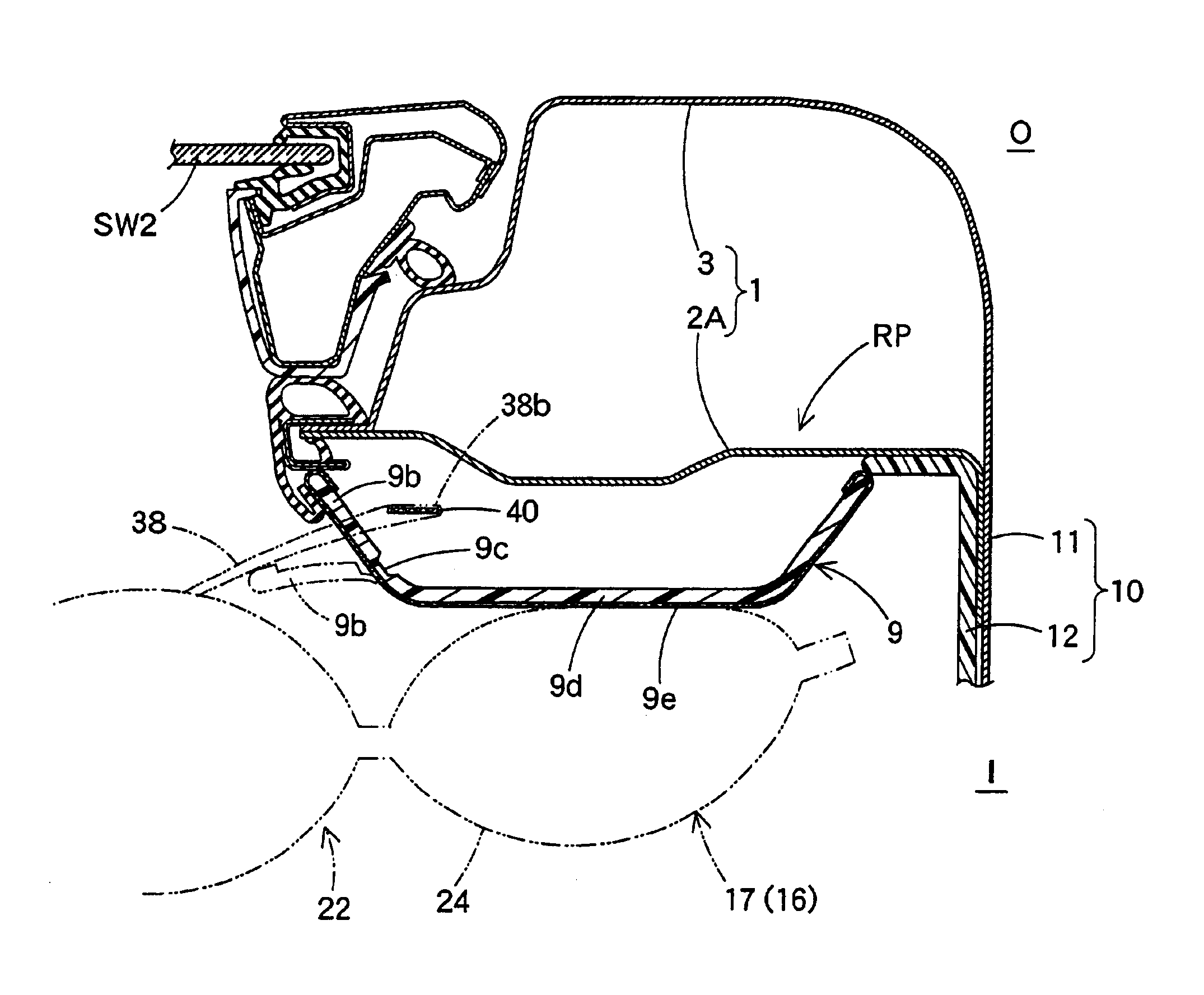
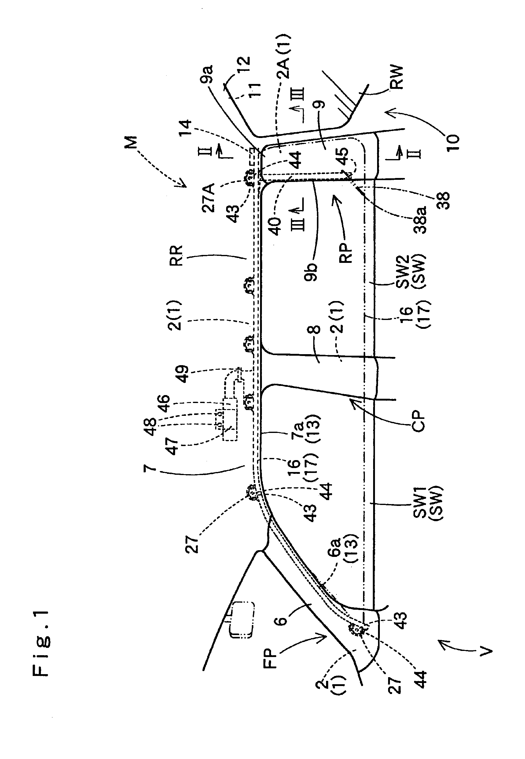
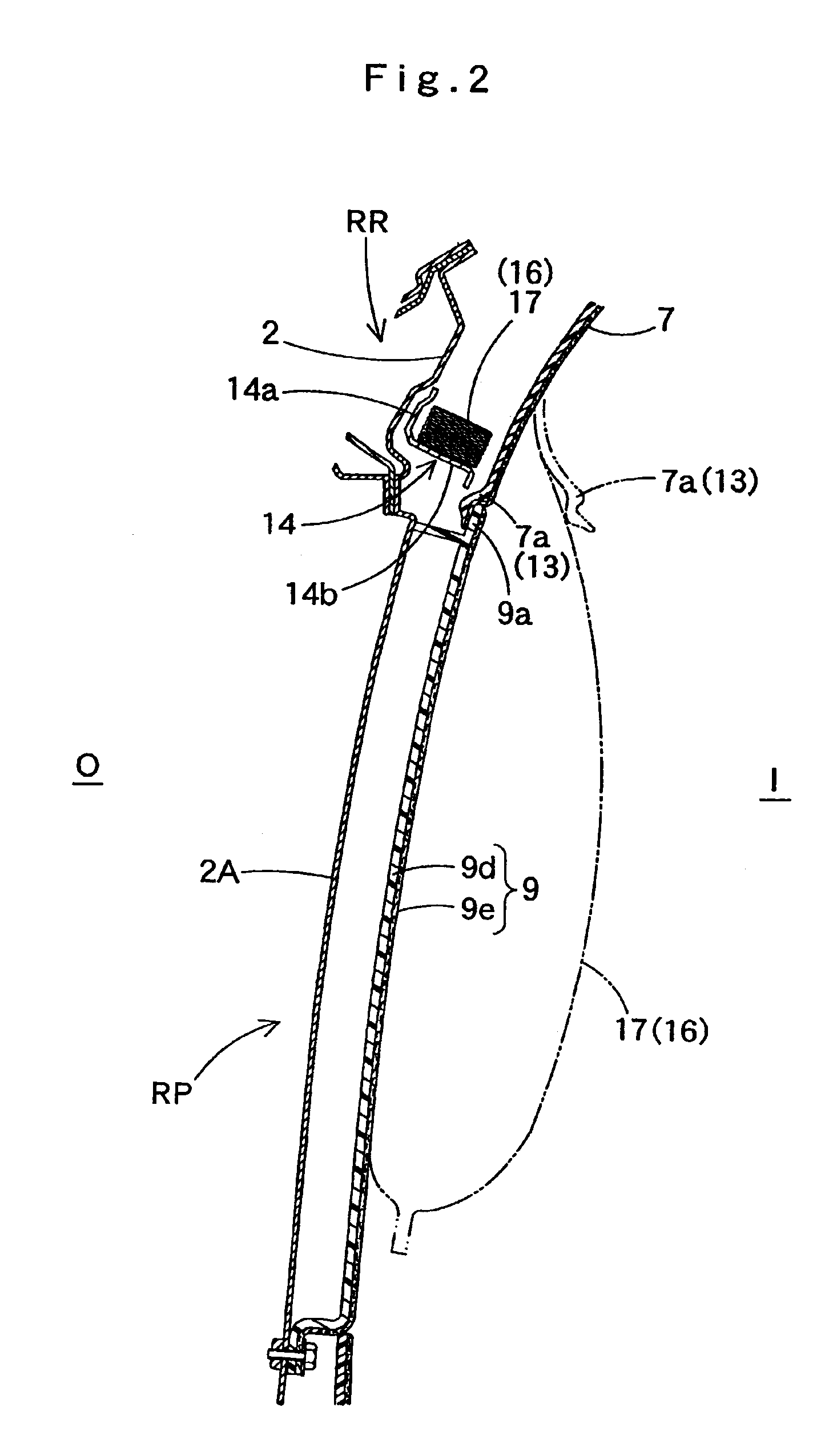
A head protecting airbag device M, as shown in FIG. 1, is mounted on a double-cab vehicle V. The head protecting airbag device M is provided with an airbag 16, a guide member 40, an inflator 46 and an airbag cover 13.

Here, the double-cab vehicle V is provided with side windows SW (SW1 and SW2) positioned on the vehicular side face, and a rear wall portion 10 arranged on the rear side of the window SW2 and generally at a right angle with respect to the window SW2. The windows SW1 and SW2 are arranged sideways of the front and rear seats for passengers. The double-cabin vehicle V is further provided wi...


PUM


Abstract

A head protecting airbag device of the invention is provided with an airbag which expands to cover the vehicular interior sides of a window and a pillar garnish. Near the front or rear edge of an inner panel, a guide member is so arranged in the vertical direction that its vehicular interior side is covered by the edge portion of the pillar garnish. A flexible connection member, which is slidably connected to the guide member, is connected to a portion of the airbag toward the center of the window. Moreover, the connection member pushes open the edge portion of the pillar garnish toward the vehicular interior side as the connection member slides downward along the guide member when the airbag expands.

Description

This application claims priority from Japanese patent application of Ogata, filed Mar. 20, 2002, No.2002-77813, the complete disclosure of which is hereby incorporated into the present application by this reference.BACKGROUND OF THE INVENTION1. Field of the InventionThe present invention relates to a head protecting airbag device provided with an airbag which is folded and housed on the upper edge of a window on the interior side of a vehicle so that it can expand and inflate downward from the upper edge of the window when it admits inflating gas, to cover the vehicular interior side of the window. More particularly, the invention relates to a head protecting airbag device which is constructed so that the airbag is guided by a guide member as it expands and inflates.2. Description of the Related ArtIn the related art, there is a head protecting airbag device, which has a construction disclosed in JP-A-9-249089 and so on.In this head protecting airbag device, there is arranged an air...

Claims


Application Information

Patent Timeline
Patent Type & Authority Patents(United States)
IPC IPC(8): B60R21/16B60R21/20B60R21/213B60R21/233
CPCB60R21/213B60R21/232B60R21/2338B60R21/215B60R2021/23386B60R2021/161B60R2021/23316
Inventor OGATA, TETSUYA
Owner TOYODA GOSEI CO LTD
Why Eureka
Try Eureka