A flexible solar wing elastic stretching rod repetitive unfolding and retracting mechanism

A flexible and elastic technology, which is applied in the field of flexible solar wing elastic stretching rod repeated expansion and retraction mechanism, can solve the problems of large retraction envelope, heavy weight, and low specific power, and achieve small retraction envelope, lighten weight and increase specific power Effect

Active Publication Date: 2018-12-28
HARBIN INST OF TECH
View PDF6 Cites 14 Cited by
  • Summary
  • Abstract
  • Description
  • Claims
  • Application Information

AI Technical Summary

Problems solved by technology

[0003] In order to solve the problems that the existing rigid and semi-rigid solar wings use one-sided deployment, which has a large folding envelope, heavy weight, and low specific power, the present invention further provides a flexible solar wing elastic extension rod repeating expansion and retraction mechanism

Method used


Image

  • A flexible solar wing elastic stretching rod repetitive unfolding and retracting mechanism
  • A flexible solar wing elastic stretching rod repetitive unfolding and retracting mechanism
  • A flexible solar wing elastic stretching rod repetitive unfolding and retracting mechanism

Examples


specific Embodiment approach 1

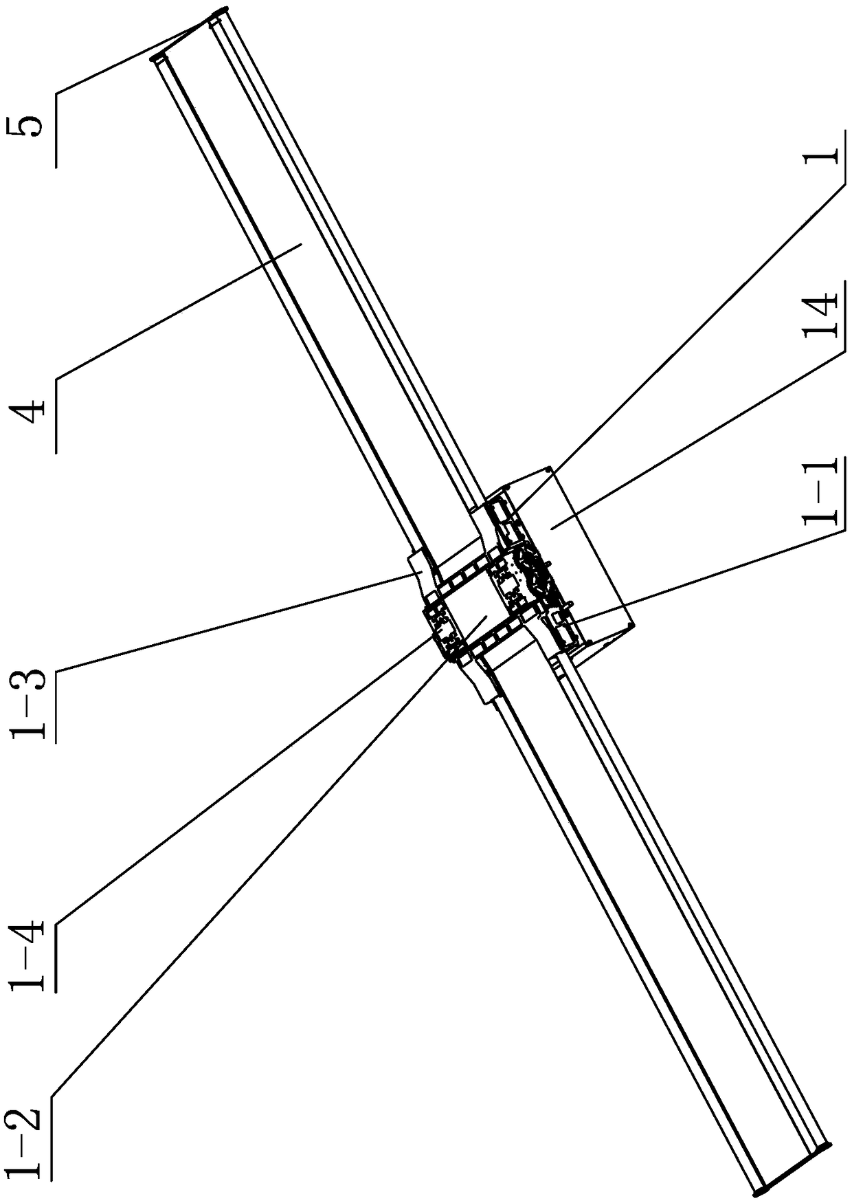
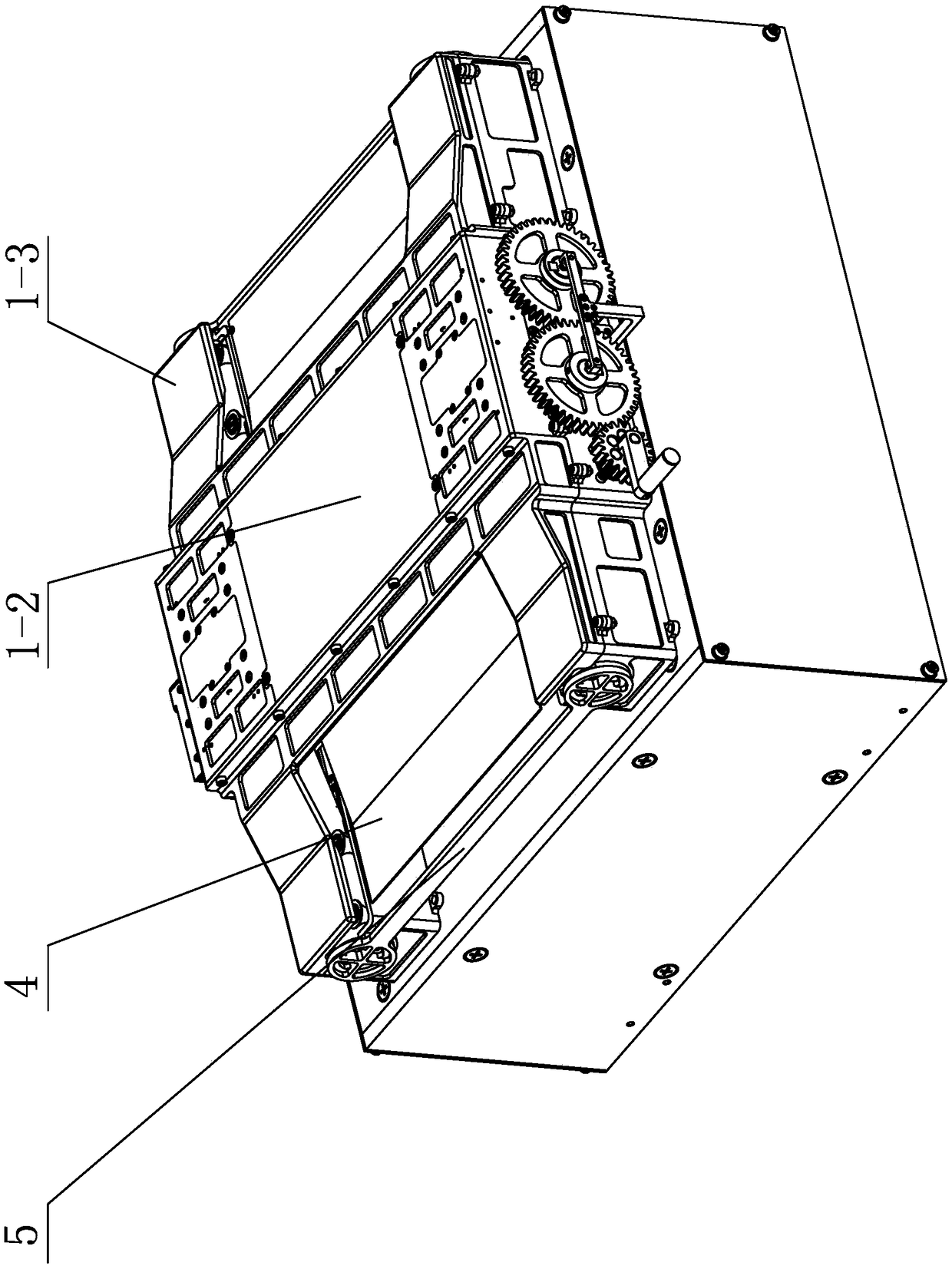
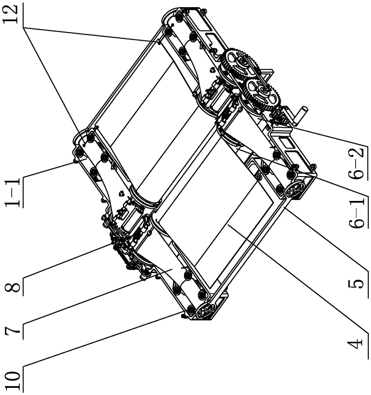
[0037] Specific implementation mode one: combine figure 1 , figure 2 , image 3 , Figure 4 , Figure 6 , Figure 9 , Figure 11 , Figure 13 , Figure 14 and Figure 15 Describe this embodiment, a flexible solar wing elastic extension rod repeating retraction mechanism in this embodiment, which includes a support truss 1, an initial compression release device 2, an electric recovery drive device 3, two flexible solar blankets 4, two Unfolding fixing frame 5, two retracting roller force transmission devices 6, four expanding rods 7, four expanding rod pressing devices 8, four initial driving devices 9, four expanding rod guiding devices 10, four sets of expanding rod heating a device 11 and a plurality of ropes 12;

[0038] Two gathering roller power transmission devices 6 are fixed side by side on the upper end surface of the installation base 1-1 of the support truss 1 along the width direction of the support truss 1, and two flexible sun blankets 4 are positioned ...

specific Embodiment approach 2

[0044] Specific implementation mode two: combination Figure 6 Illustrate this embodiment, each retracting roller force transmission device 6 of this embodiment also includes two connecting flanges 6-3 and two heat insulation pads 6-4, two unfolding rods retracting rollers 6-2 and The gathering rollers 6-1 of the sun blanket are connected by the gathering roller flanges, and a wire groove 6-5 for installing the rope 12 is set on the said gathering roller flange along the length direction, and each unfolding rod gathers the rollers A thermal insulation pad 6-4 is provided at the connection between 6-2 and the sun blanket retracting roller 6-1, and a connection flange 6-3 is provided at the free end of each unfolding rod retracting roller 6-2. In such a setting, in the folded state, the flexible sun blanket 4 and the connecting flange 6-3 are designed with a wiring groove 6-5, and the distance between the ropes 12 is determined by the number of winding turns and the position of ...

specific Embodiment approach 3

[0046] Specific implementation mode three: combination Figure 7 and Figure 8 To illustrate this embodiment, each deployment rod guide device 10 of this embodiment includes an inner guide cylinder 10-1, a guide wheel shaft 10-2, four guide wheels 10-3, a guide bracket 10-4 and a shaft sleeve, and the inner guide cylinder 10-1 is installed on the guide bracket 10-4 along the length direction of the guide bracket 10-4, the four guide wheels 10-3 are symmetrically arranged on both sides of the inner guide cylinder 10-1, and the guide wheels 10-3 are installed with bushings Each guide wheel 10-3 is rotationally connected with the guide bracket 10-4 through the guide wheel shaft 10-2, the inner guide cylinder 10-1 is in clearance fit with the inner side of the deployment rod 7, and the four guide wheels 10-3 are connected with the outer surface of the deployment rod 7 With loose fit, the guide bracket 10-4 is fixedly connected with the installation base 1-1. In this way, the dep...


PUM


Abstract

The invention relates to a flexible solar wing elastic stretching rod repetitive unfolding and retracting mechanism, which relates to the field of aerospace space mechanism. The invention solves the problems of large folding envelope, heavy weight and low specific power of the prior rigid and semi-rigid solar wing which adopts the unilateral deployment mode. The two force transmission devices of the invention are fixed on the mounting base side by side, A deployment bar is arranged on both sides of the flexible solar blanket, A flexible solar blanket is connected to the deployment lever by a rope, At that end of the flexible solar blanket is wound up on a solar blanket take-up roll, At that end of the unwrap bar is wound up on the unwrapping bar take-up drum, A distal end of that deployment bar is press against the deployment bar retracting roll by a deployment bar pressing device, Four unfolding bar guides correspond to four unfolding bars one by one. An initial driving device is arranged inside the inner guide cylinder of the unfolding bar guide. An initial pressing and releasing device is installed at one end of the force transmission device of the unfolding roller, and an electric recovery driving device is installed at the other end of the force transmission device of the unfolding roller. A space power supply for a spacecraft is provided.

Description

technical field [0001] The invention relates to the field of aerospace space mechanisms, in particular to a mechanism for repeatedly expanding and retracting elastic stretch rods of flexible solar wings. Background technique [0002] With the increasing demands of space missions, the technology of spacecraft mechanism has been paid more and more attention. The solar wing is a main form of space power supply for the spacecraft, and it is also the most important and typical deployment part on the spacecraft. Considering the space limitation of the vehicle and the large overload during the launch process, the solar wings of the spacecraft during the launch phase are generally in a folded state, and can only be unlocked and deployed after the spacecraft is separated from the vehicle and enters a free flight orbit. When the solar wings are successfully deployed and locked, the spacecraft can gain enough energy to ensure normal operation. Therefore, the deployment and locking of...

Claims


Application Information

Patent Timeline
Patent Type & Authority Applications(China)
IPC IPC(8): B64G1/44
CPCB64G1/443
Inventor 郭宏伟邓宗全刘荣强李永永杨德文
Owner HARBIN INST OF TECH
Why Eureka
Try Eureka