Muzzle brake with propelling nozzle for recoil control

a technology of recoil control and muzzle brake, which is applied in the direction of muzzle attachment, weapons, weapons types, etc., can solve the problems of high undesirable recoil, difference between winning or losing in professional shooting competitions, and any innocent being protected and possible innocent bystanders, so as to avoid recoil and minimize recoil , the effect of more accurate delivery of the projectile to a particular intended targ

Active Publication Date: 2018-12-18
PRICE DONALD H
View PDF9 Cites 13 Cited by
  • Summary
  • Abstract
  • Description
  • Claims
  • Application Information

AI Technical Summary

Benefits of technology

[0053]Another object of the present invention is to provide a firearm which avoids recoil or minimizes recoil.
[0054]Another object of the present invention is to provide a firearm which can remain aimed more precisely at a target immediately after firing of the firearm, such that further shots immediately after projectile discharge will have a greater tendency to strike close to the target.
[0055]Another

Problems solved by technology

This recoil is highly undesirable as it throws off the aim of the user.
As stated above, it is this destruction of the sight picture and the critical delay in reacquiring it before firing again, that endangers the user, any innocents being protected and possible innocent bystanders.
This delay can also mean the difference between winning or losing in professional shooting competitions.
Especially with handguns, which shoot a less powerful bullet, failure to achieve rapid fire accuracy can be a great danger to the user and any innocents who the user is attempting to protect.
In addition, innocent bystanders may be in danger from stray shots occurring due to the recoil effect throwing off the aim of the user.
As stated above, it is this critical delay that endangers the user, any innocents being protected and possible innocent bystanders.
The current devices available are less efficient than desired and tend to be bulky and expensive, as well as potentially interfering with the function of the gun.
For these and perhaps other reasons, such muzzle brake devices are only seen on a small fraction of pistols and revolvers available commercially and are especially rare or non-existent on police or military weapons.
Although “muzzle brakes” are seen more commonly on rifles, the prior art is similarly less efficient than desired.
Great care must be taken to screw the brake on to the proper depth and position and it must be secured properly or there is a risk it will come loose during repeated firing, possibly endangering the user and other bystanders.
This is primarily because the prior art muzzle brakes do not use true propelling nozzles that are scientifically designed to facilitate and maximize the conversion of heat energy into velocity.
In contrast, the baffle plates, fins, square bottomed slots, ports, etc., actually interfere with this process.
These obstructions create, in the words of rocket science, “friction, flow disturbances and shock losses” wh

Method used


Image

  • Muzzle brake with propelling nozzle for recoil control
  • Muzzle brake with propelling nozzle for recoil control
  • Muzzle brake with propelling nozzle for recoil control

Examples


Embodiment Construction

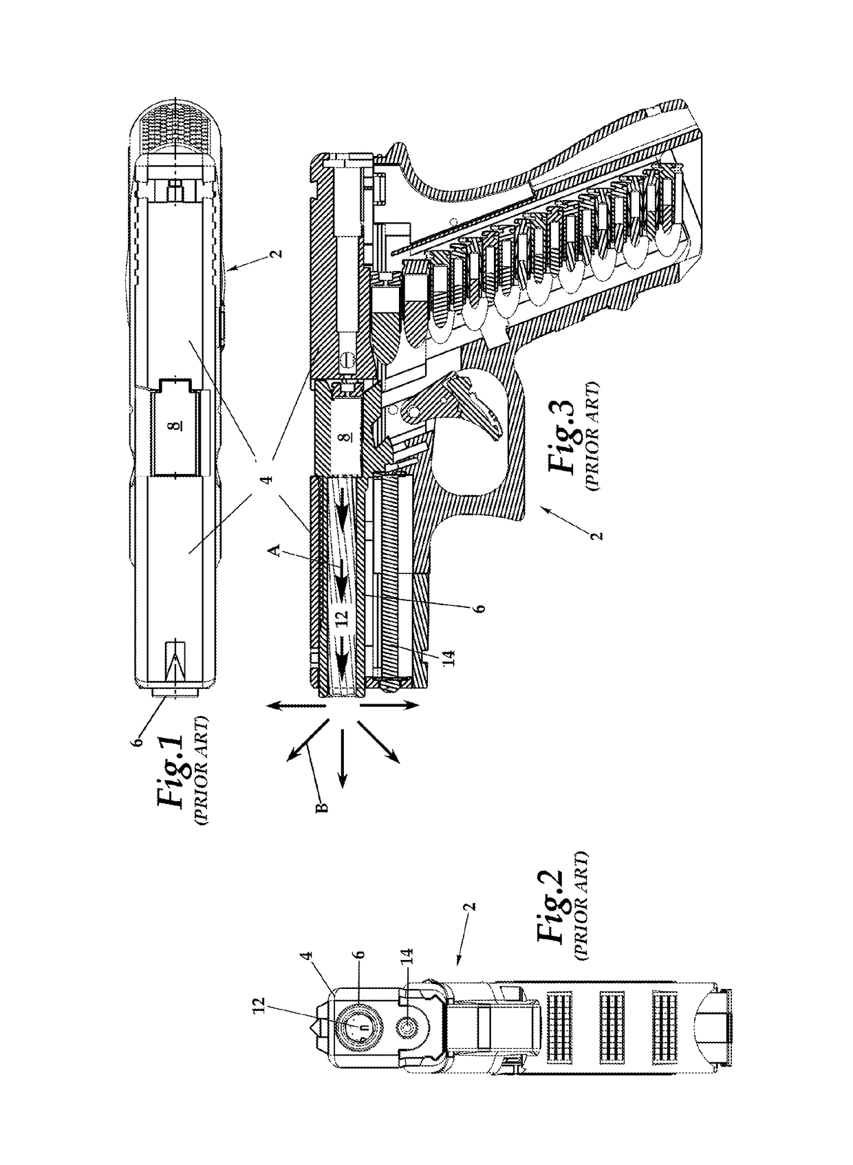
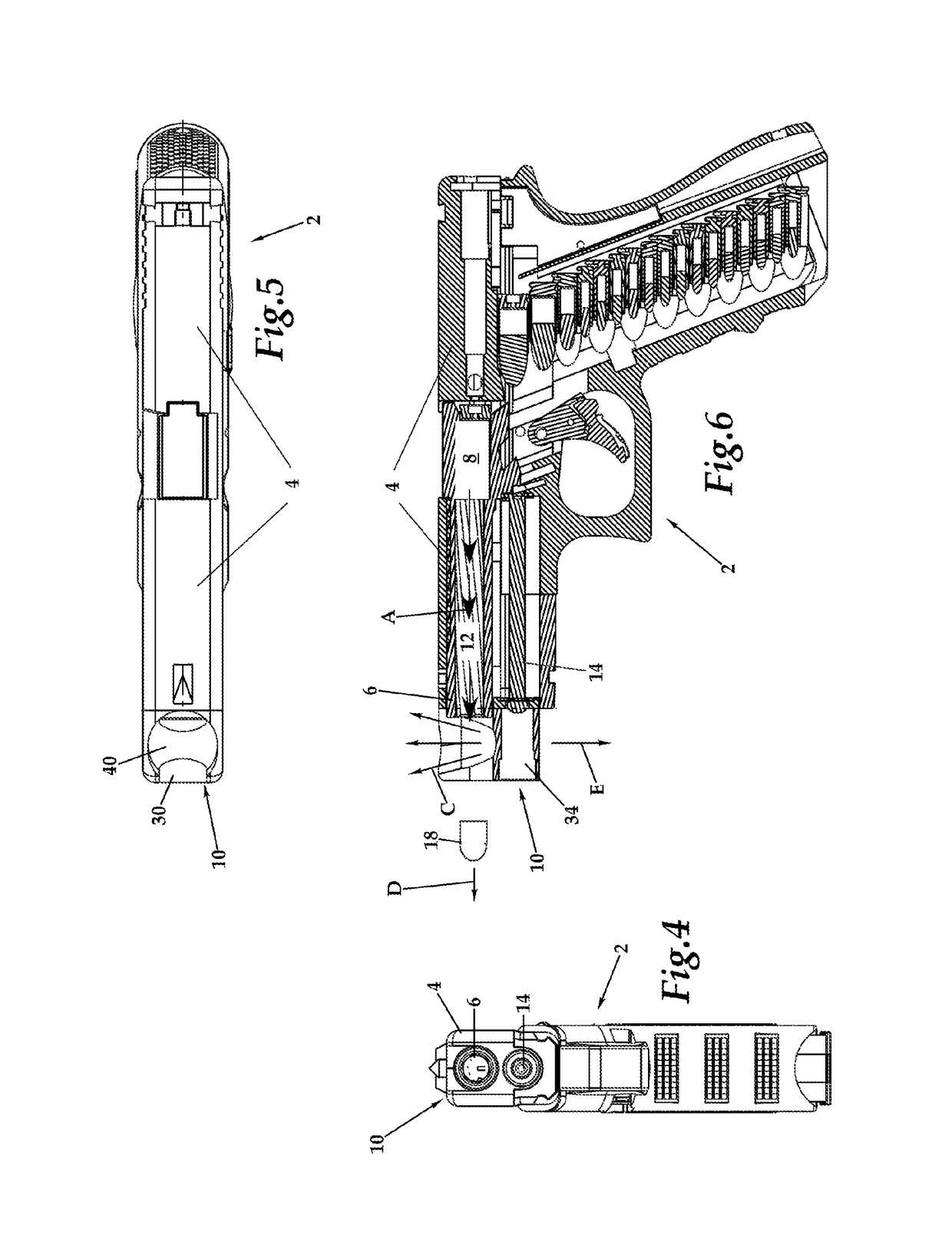
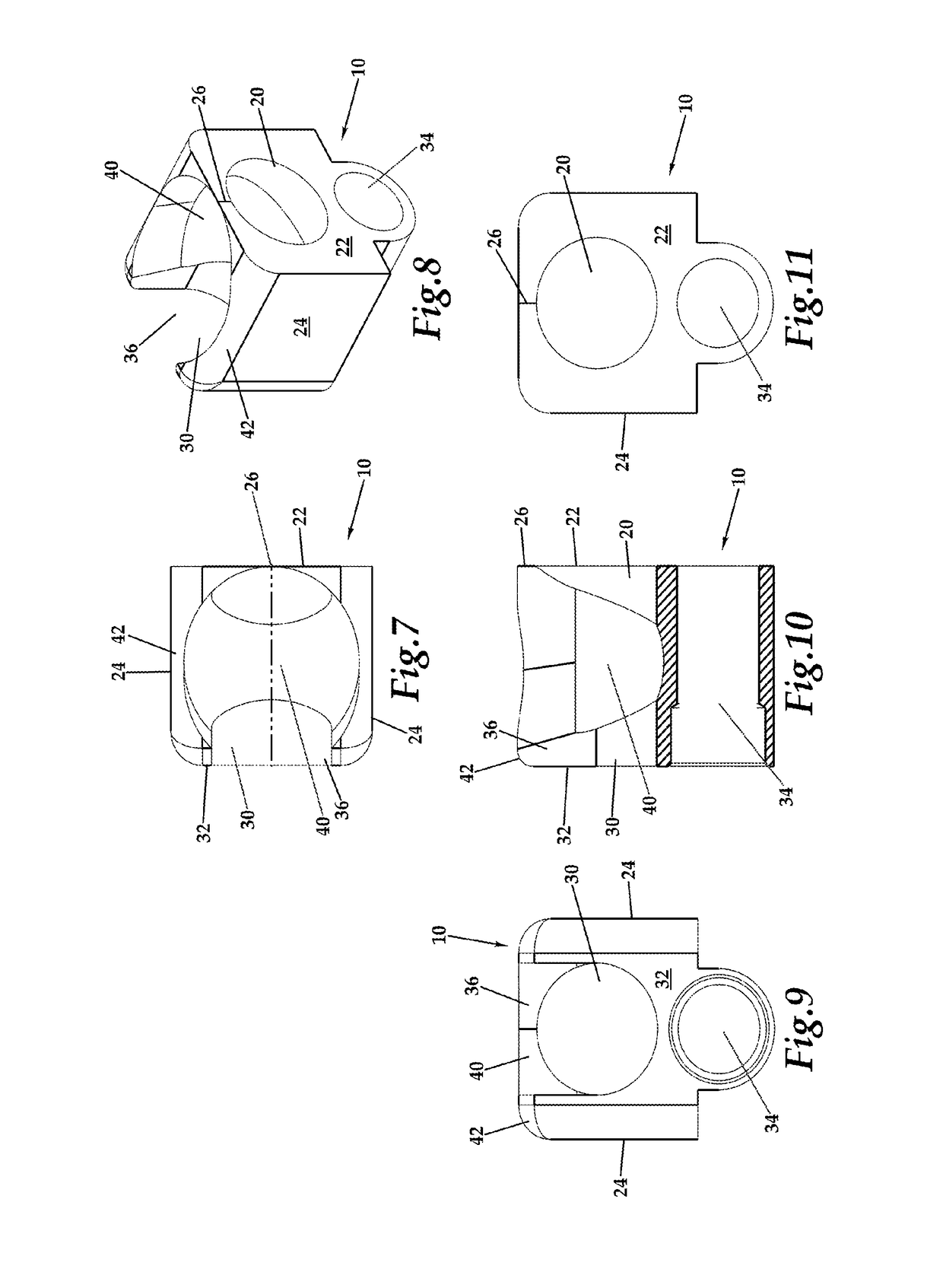
[0130]Referring to the drawings, wherein like reference numerals represent like parts throughout the various drawing figures, reference numeral 10 is directed to a muzzle brake (FIGS. 4-11) which can be built into a handgun or other firearm (such as a pistol 2), or attached to a muzzle end of a barrel 6 of the pistol 2 (or other firearm). The muzzle brake 10 focuses expanding projectile motion gases through a propelling nozzle 40 to at least partially counteract recoil of the firearm.

[0131]In essence, and with particular reference to FIGS. 4-11, basic details of this invention are described, according to a first and generally preferred embodiment. In this embodiment, the muzzle brake 10 is shown attached to a pistol 2 (FIGS. 1-3) of a generally semi-automatic variety having a slide 4 and barrel 6 extending forwardly relative to a chamber 8. A bore 12 of the pistol 2 is typically rifled to cause a bullet 16 discharged through the bore 12 to travel along a straighter trajectory (along...


PUM


Abstract

The muzzle brake attaches to a distal end of the barrel of a firearm, typically a handgun, either built into the firearm or as an accessory attachable to the firearm. The muzzle brake includes a propelling nozzle in the form of a central chamber aligned with proximal and distal openings aligned with a barrel of the firearm. This propelling nozzle extends upward, generally expanding in cross-section, to a rim where it opens above the firearm near a distal end of the barrel. The shape of the propelling nozzle (or series of nozzles) is preferably selected to optimize downward reactive force when expanding gases discharged from firearm discharge expand upward out of the propelling nozzle. A downward reactive force is thus created which counteracts recoil of the firearm.

Description

CROSS-REFERENCE TO RELATED APPLICATIONS[0001]This application claims benefit under Title 35, United States Code § 119(e) of U.S. Provisional Application No. 62 / 366,505 filed on Jul. 25, 2016.FIELD OF THE INVENTION[0002]The following invention relates to recoil control devices for firearms. More particularly, this invention relates to devices which attach to or are built into a distal end of a barrel of a firearm, or its frame, and which use a propelling nozzle to maximize the velocity redirection of expanding gases from a firearm discharge to compensate for firearm recoil.BACKGROUND OF THE INVENTION[0003]Firearms accommodate firing a bullet (or other projectile) from a cartridge filled with a propellant charge, inserted into a “chamber” of the firearm which, when ignited, creates a high pressure, high temperature gas. This high pressure gas is contained by the cartridge and the chamber of the firearm, so the path of least resistance is to push the bullet into a barrel of the firearm...

Claims


Application Information

Patent Timeline
IPC IPC(8): F41A21/36F41C3/00
CPCF41A21/36F41C3/00
Inventor PRICE, DONALD H.
Owner PRICE DONALD H
Why Eureka
Try Eureka