Movable lock catch and handheld circular saw

A technology of movable locks and circular saws, which is applied in the direction of portable motorized devices and manufacturing tools, can solve the problems of limited anti-recoil effect, low reliability of anti-recoil mechanism, and inflexible and convenient configuration of anti-recoil lock blocks, etc. To achieve the effect of flexible and quick installation

Active Publication Date: 2013-11-27
SUMEC HARDWARE & TOOLS
View PDF7 Cites 4 Cited by
  • Summary
  • Abstract
  • Description
  • Claims
  • Application Information

AI Technical Summary

Problems solved by technology

However, the reliability of the existing anti-recoil mechanism is not high, and the anti-recoil effect is limited. For example, the anti-recoil lock block adopted in the European patent E

Method used


Image

  • Movable lock catch and handheld circular saw
  • Movable lock catch and handheld circular saw
  • Movable lock catch and handheld circular saw

Examples


Embodiment 1

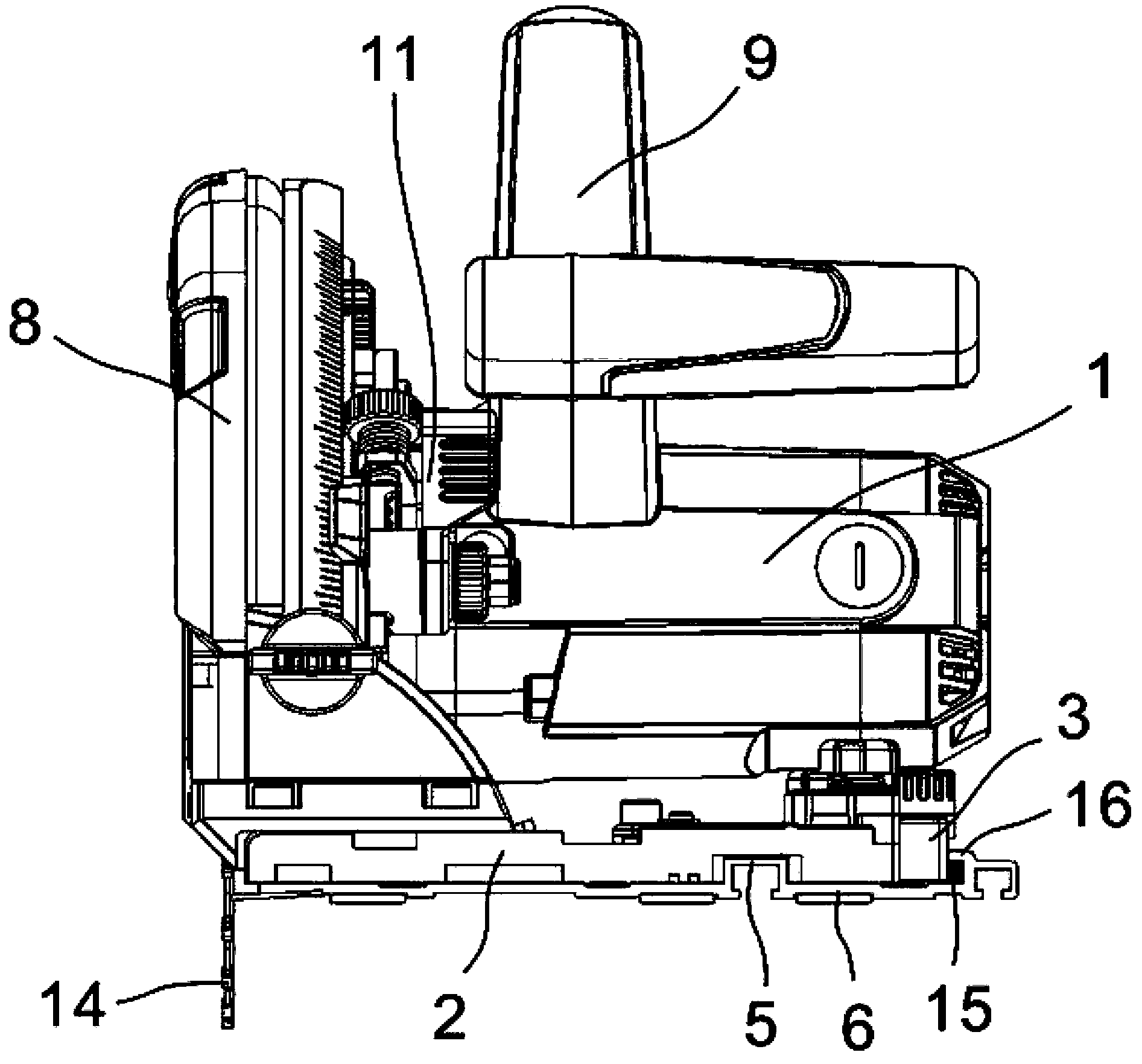
[0042] Such as Figure 4 , 5 , Figure 7 As shown, the movable lock 3 of the present invention can be used on a hand-held circular saw, and includes: a lock block seat 18 , a rotating shaft 17 and a knob 19 . The lock block seat 18 is provided with a through hole that can accommodate the passage of the rotating shaft 17; one end of the rotating shaft 17 passes through the lock block seat 18 and is connected with the knob 19. In order to prevent the knob 19 from breaking away from the rotating shaft 17, an elastic stopper is arranged on the rotating shaft 17 above the knob 19. Ring 20, and a knob cover 21 connected to the top of the knob 19 is arranged outside the circlip 20. The other end of the rotating shaft 17 is provided with a square head lock block 15. The head of the square head lock block 15 is square, and the rotating shaft 17 rotates with the rotation of the knob 19. Or stretch out the lock block seat 18 outside.

[0043] The lock block seat 18 can be connected a...

Embodiment 2

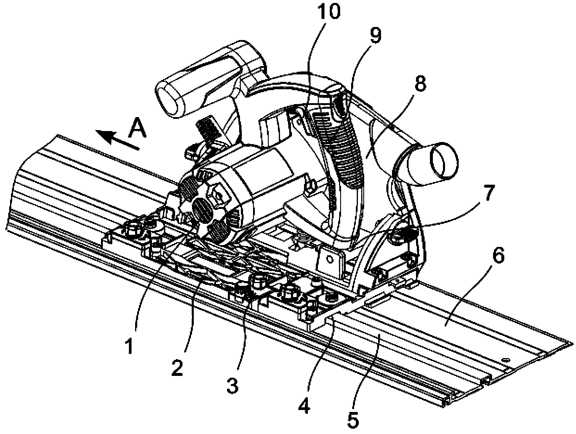
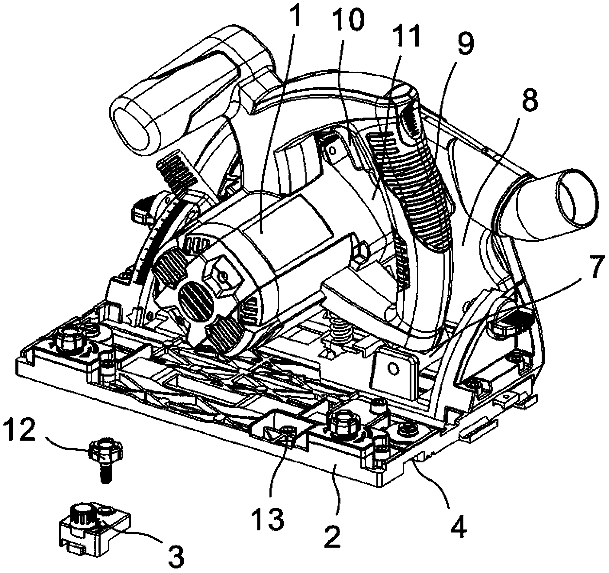
[0047] Such as figure 1 , 2 , 3 and 6, the hand-held circular saw with movable lock includes: housing 1, gearbox 11, saw blade 14, main handle 9, base 2, protective cover 8 and hinge mechanism 7.

[0048]The housing 1 is used to accommodate the motor; the gearbox 11 is used to accommodate the speed change mechanism, one end of the speed change mechanism is connected with the motor, and the other end is connected with the output shaft; the saw blade 14 is connected with the output shaft; the main handle 9 is provided with a machine switch 10 . The base 2 has a lower surface suitable for sliding on the workpiece or the guide rail 6 , and has a groove 4 on the lower surface, and the groove 4 can cooperate with the corresponding linear track 5 on the guide rail 6 . The protective cover 8 is arranged on one side above the base 2 , and the protective cover 8 can be turned over at a certain angle to the side of the base 2 , and the protective cover 8 can accommodate the saw blade 14...


PUM


Abstract

The invention provides a movable lock catch and a handheld circular saw with the same. The movable lock catch comprises a locking piece seat, a rotating shaft and a connecting fastener, a via hole capable of allowing a rotating shaft to pass through is formed in the locking piece seat, one end of the rotating shaft penetrates the locking piece seat to be connected with a knob and rotates with the knob, the other end of the rotating shaft is provided with a square-head locking piece with a square head, the square head rotates with the rotating shaft to the inside of the locking piece seat or extend out of the locking piece seat when the rotating shaft rotates, and the locking piece seat is fixed on a to-be-locked device by the connecting fastener. The movable lock catch cuts forward together with the circular saw along a guide rail; when the movable lock catch is at an open position, the circular saw is allowed to move along a cutting direction of the guide rail and is prevented from leaving the guide rail to move towards a direction of a user; when backlash happens, the circular saw is limited on the guide rail by the movable lock catch. The handheld circular saw is safer and more reliable to operate.

Description

technical field [0001] The invention relates to a movable lock used for a hand-held circular saw, and the movable lock is especially suitable for a circular saw with a plunge-type cutting action. Background technique [0002] For hand-held circular saws with plunge feed, when the rotating saw blade cuts into the workpiece, it will generate a recoil, and the resulting recoil force will cause the circular saw to leave the guide rail and fly towards the user. In order to prevent the circular saw from leaving the guide rail and moving towards the user, an anti-recoil mechanism is usually used. When the recoil occurs, the anti-recoil mechanism will limit the circular saw to the guide rail, making the operation of the hand-held circular saw safer and easier. reliable. However, the reliability of the existing anti-recoil mechanism is not high, and the anti-recoil effect is limited. For example, the anti-recoil lock block adopted in the European patent EP1418018B1 limits the anti-r...

Claims


Application Information

Patent Timeline
IPC IPC(8): B25F5/00
Inventor 林有余
Owner SUMEC HARDWARE & TOOLS
Why Eureka
Try Eureka