Charging detection system of battery pack

A charging detection and battery pack technology, applied in the direction of measuring electricity, measuring devices, measuring electrical variables, etc., can solve problems such as endangering life and property safety, safety accidents, battery recoil, etc., to avoid short circuit phenomenon, protect safety, and ensure safety effect

Active Publication Date: 2014-03-12
MICROVAST
View PDF5 Cites 4 Cited by
  • Summary
  • Abstract
  • Description
  • Claims
  • Application Information

AI Technical Summary

Problems solved by technology

[0003] However, in actual operation, each battery pack corresponds to a small current supplementary device, which is impossible in terms of cost and system complexity, so there is an urgent need for a battery pack that can easily and effectively supplement energy. equipment; in the prior art, a current supplementary device is used to charge the entire battery pack, and the current supplementary device can evenly charge multiple strings of batteries by switching, that is, in the form of a relay array, as long as it is through the relay array Regardless of the array mode, there is a process of switching from one string of batteries in the battery pack to another through relays, so the following situations may occur in this process: the control signal achieves successful switching, but due to Long-term and high-frequency switching of the relay leads to failure and sticking together, which may cause two strings of batteries to short-circuit through the relay, resulting in accidents; on the other hand, due to the battery power distribution, it is necessary to lead the wiring harness from each battery unit in the battery pack Connect the charging equipment separately, the complexity of the wiring harness can be imagined, the possibility of connection error is very high, if there is a wrong connection, it may cause recoil to the battery or a direct short circuit phenomenon, which may easily cause safety accidents and endanger life property safety

Method used


Image

  • Charging detection system of battery pack
  • Charging detection system of battery pack

Examples


Embodiment Construction

[0038] The specific embodiments of the present invention will be described in detail below in conjunction with the accompanying drawings.

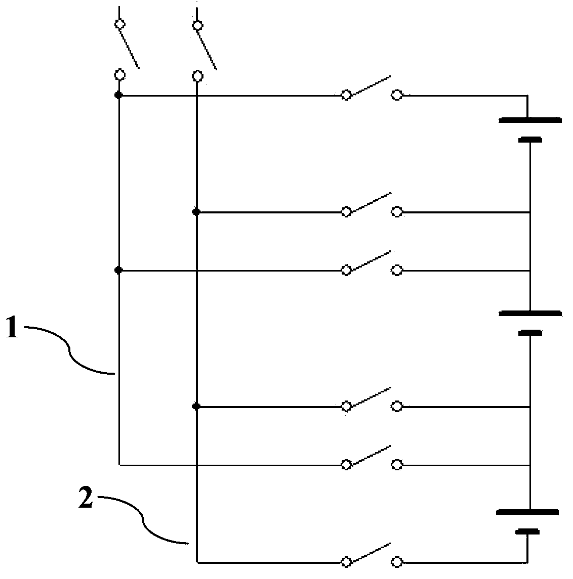
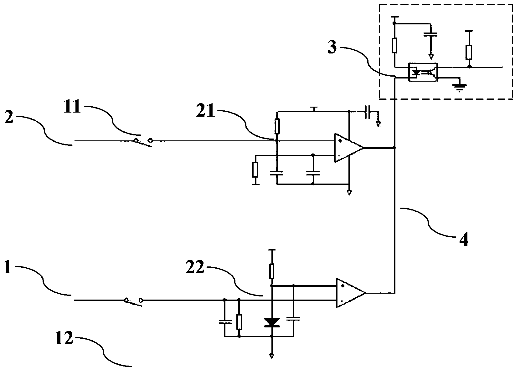
[0039] Such as Figure 1-Figure 2 As shown, the present invention includes a charging module, a common bus positive 1, a common bus negative 2, a relay, a battery pack composed of 8 3.2V battery modules, and a circuit detection system. The common bus positive 1 is connected to the positive terminal of the battery pack. Bus negative 2 is connected to the negative terminal of the battery pack, and the charging module is connected to common bus positive 1 and common bus negative 2. The common bus positive 1 is provided with the same number of battery modules and connected to the positive pole of the battery module, and the common bus negative 2 is set The negative branch line with the same number of battery modules and connected to the negative electrode of the battery module. The positive branch line and the negative branch line are respectivel...


PUM


Abstract

Provided in the invention is a charging detection system of a battery pack. The charging detection system comprises a charging module, a common bus positive end, a common bus negative end, a relay, a batter pack formed by a plurality of battery modules, and a circuit detection system. The common bus positive unit is connected with a positive terminal of the battery pack; and the common bus negative unit is connected with a negative terminal of the battery pack. The common bus positive unit is provided with positive branch lines that are connected with positive electrodes of the battery modules, wherein the number of the positive branch lines are identical with that of the battery modules; and the common bus negative unit is provided with negative branch lines that are connected with negative electrodes of the battery modules, wherein the number of the negative branch lines is identical with that of the battery modules. According to the technical scheme, when charging equipment is used for charging the battery pack, a short circuit phenomena caused by relay aging can be effectively avoided; secure switching of the battery modules in the large battery pack can be realized; the connection error of the charging circuit can be prevented; inverse charging of the battery can be avoided and the direct short-circuit phenomenon can be prevented; security during the whole charging process can be ensured; and the human life and property security can be protected.

Description

Technical field [0001] The invention relates to a charging detection system. Background technique [0002] The traditional lithium-ion battery pack is composed of several battery packs in series and parallel. After the battery pack is charged and discharged for a long time, the battery packs of the battery pack are prone to cause imbalance, so when the battery pack is used for a period of time, it is necessary It is balanced to recharge it. The usual recharge method is to continue to charge it with a smaller current and fully charge the under-charged battery, which can restore the battery pack to its original state of use and increase application performance and service life. [0003] However, in actual operation, each battery pack corresponds to a small current supplementary device, which is impossible regardless of the cost or the complexity of the system. Therefore, there is an urgent need for a battery pack that can easily and effectively supplement energy. In the prior art, a...

Claims


Application Information

Patent Timeline
Patent Type & Authority Applications(China)
IPC IPC(8): G01R31/36
Inventor 陈艇王云杰严国刚
Owner MICROVAST
Why Eureka
Try Eureka