
Rail lamp light performance system

A track and lighting technology, which is applied in the field of track lighting performance system, can solve the problems of monotonous performance of light-emitting components, failure to realize power supply, fixed track cannot be moved, etc.

Active Publication Date: 2019-05-03
GUANGZHOU LEAFUN CULTURE SCI & TECH
View PDF6 Cites 1 Cited by
  • Summary
  • Abstract
  • Description
  • Claims
  • Application Information

AI Technical Summary

Problems solved by technology

[0003] Existing stage sound and light shows generally fix the performance device on the track for rotation and up-and-down performance. Generally, the light-emitting components are lanterns or lotus lanterns and other aesthetic light-emitting lamps. The fixed track cannot be moved, and the light-emitting components are fixed The performance method of rotating and lifting the position is relatively monotonous, which cannot well present the effect of the sound and light show to the audience; at the same time, the existing sound and light show can only move on the land track, and the power supply guide rail can only meet the requirements of the land lighting components. For some light-emitting components that need to perform on the water, power supply cannot be realized. In addition, the existing sound and light show uses a motor to directly drive the light-emitting component to move, and the motor directly drives the light-emitting component to be prone to bumps during operation, which in turn affects the entire sound and light show. overall effect

Method used


Image

  • Rail lamp light performance system
  • Rail lamp light performance system
  • Rail lamp light performance system

Examples


Embodiment Construction

[0028] The specific implementation manners of the present invention will be further described in detail below in conjunction with the accompanying drawings and embodiments. The following examples are used to illustrate the present invention, but are not intended to limit the scope of the present invention.

[0029] In the description of the present invention, it should be understood that the orientation or positional relationship indicated by the terms "upper", "lower", "left", "right", "top", "bottom" etc. Orientation or positional relationship is only for the convenience of describing the present invention and simplifying the description, and does not indicate or imply that the referred device or element must have a specific orientation, be constructed and operated in a specific orientation, and thus should not be construed as a limitation of the present invention.

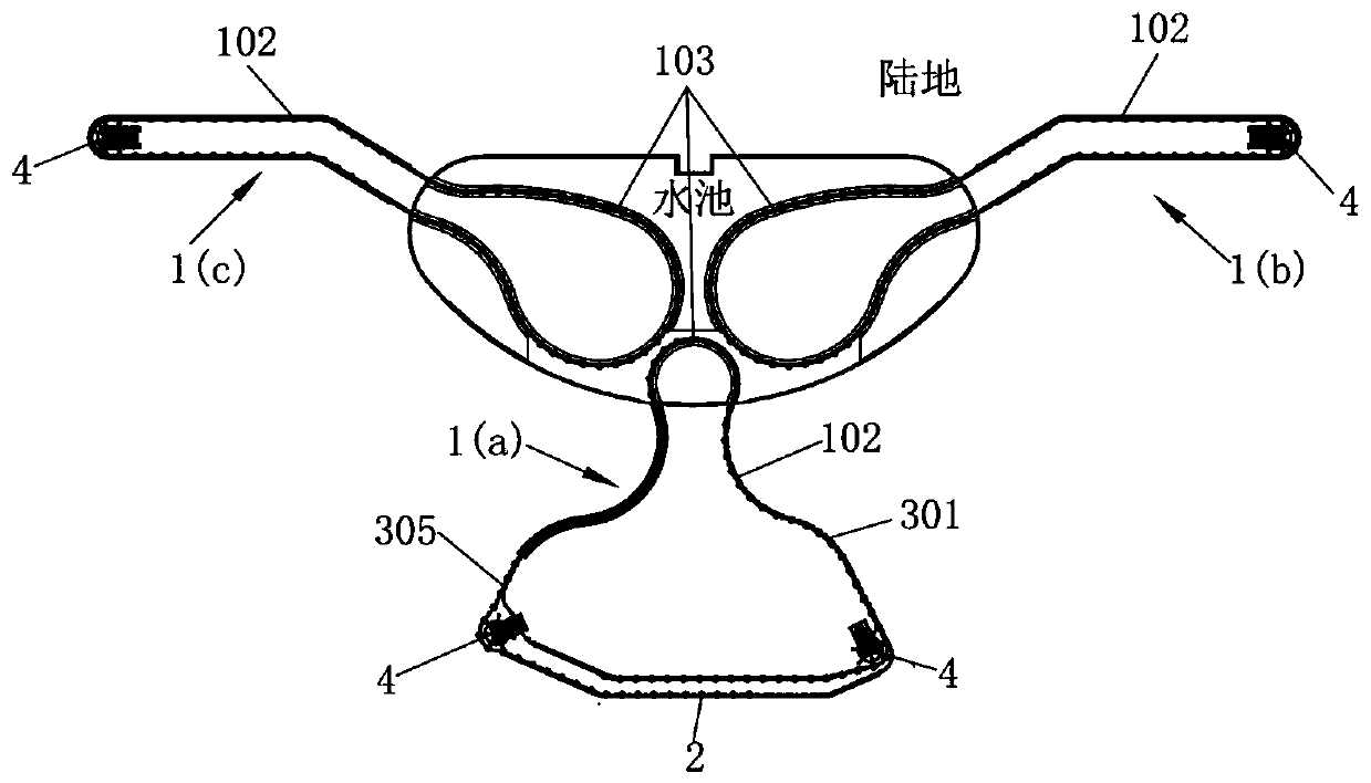
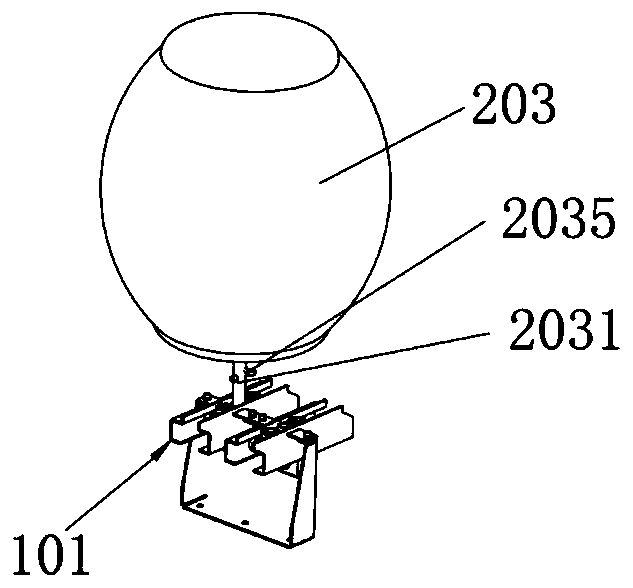
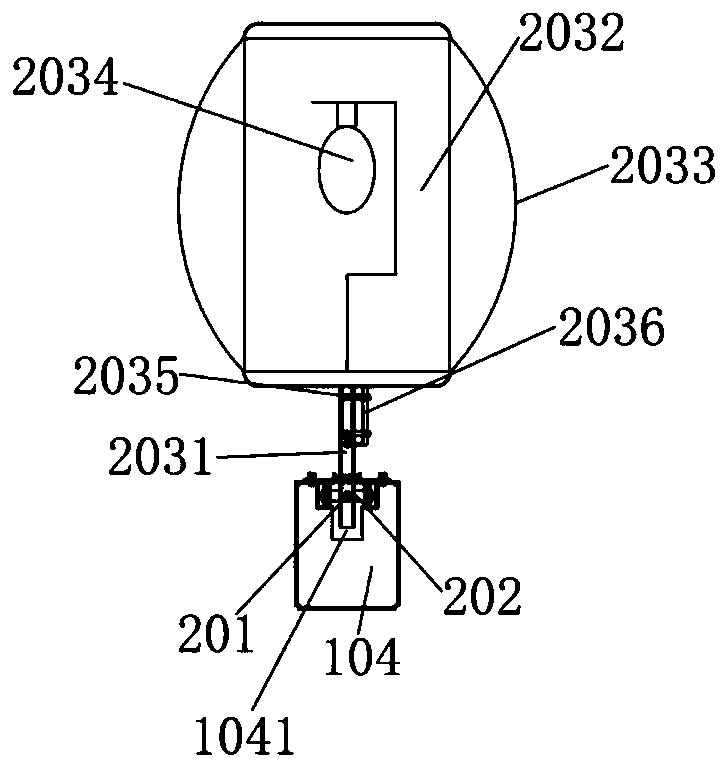
[0030] combine Figure 1-8 As shown, a track light show system schematically showing an embodiment of the pr...


PUM


Abstract

The invention relates to the technical field of sound and light show performance, and discloses a rail lamp light performance system. Transformers are arranged among a power supply guide rail, a powersupply cable and power supply equipment; through the transformers, 220V voltage is converted into safe voltage of a light emitting assembly so as to ensure the electricity use safety of the light emitting assembly; a power supply system respectively realizes the power supply on a land rail and an on-water rail through the power supply guide rail and the power supply cable; the power supply cableis used for supplying electricity to the on-water rail, so that the power supply safety can be ensured, and the influence caused by water body environment on the power supply of the light emitting assembly can be avoided; a driving assembly drives a turntable to rotate through a driving motor for further driving a pulling arm to rotate around the center of the turntable; therefore a clamping and connecting part of the pulling arm is clamped and connected onto the light emitting assembly; the light emitting assembly moves along the rail system along with the rotation of the pulling arm; the pulling arm is driven by the motor, so that the load is smaller through being compared with the condition of directly driving the light emitting assembly; the operation stability of the light emitting assembly is high; the labor saving is realized; and the effect of the sound and light show can be ensured.

Description

technical field [0001] The invention relates to the technical field of lighting performances, in particular to a track lighting performance system. Background technique [0002] Sound and light show is a form of artistic performance based on cultural themes, supported and carried by sound and light technology and equipment. Generally, high-tech audio, lighting, video, mechanical devices, fountains and waterscapes and other equipment are integrated and applied (such as large-scale performance pools, lifting stages, movable audience seats or scenery, props, etc.) to form a cultural connotation. , The way of presenting the artistic viewing effect allows the integration of culture and technology to bring the audience a shocking and gorgeous audio-visual experience and experience. [0003] Existing stage sound and light shows generally fix the performance device on the track for rotation and up-and-down performance. Generally, the light-emitting components are lanterns or lotus ...

Claims


Application Information

Patent Timeline
Patent Type & Authority Applications(China)
IPC IPC(8): F21S10/00F21V21/34F21V23/00F21V23/02F21V23/06H05B37/00
Inventor 严汉增李志雄彭泽巍李雯
Owner GUANGZHOU LEAFUN CULTURE SCI & TECH
Learn More