Communication device

a communication device and communication technology, applied in the field of communication devices, can solve the problems of inability to communicate, inability to achieve circuit matching, and unsatisfactory relief of unnecessary electromagnetic emission from the interrogator as a whol

Inactive Publication Date: 2005-03-22
ROHM CO LTD
View PDF33 Cites 42 Cited by
  • Summary
  • Abstract
  • Description
  • Claims
  • Application Information

AI Technical Summary

Problems solved by technology

However, in the non-contact communication system described above, the interrogator and the responder form a complete circuit with space interposed in between, and therefore it is difficult to achieve circuit matching.
On the other hand, by shielding the whole interrogator, as by forming the housing thereof out of metal or the like, it is possibl

Method used


Image

  • Communication device
  • Communication device
  • Communication device

Examples


first embodiment

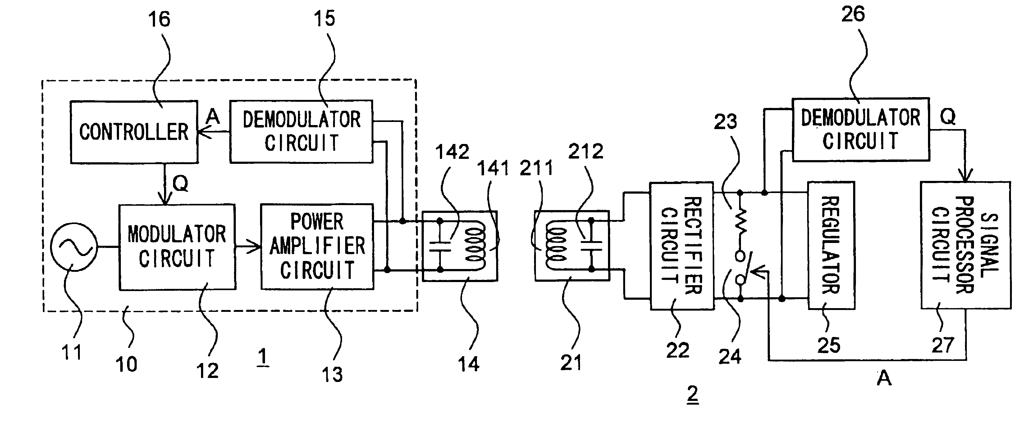
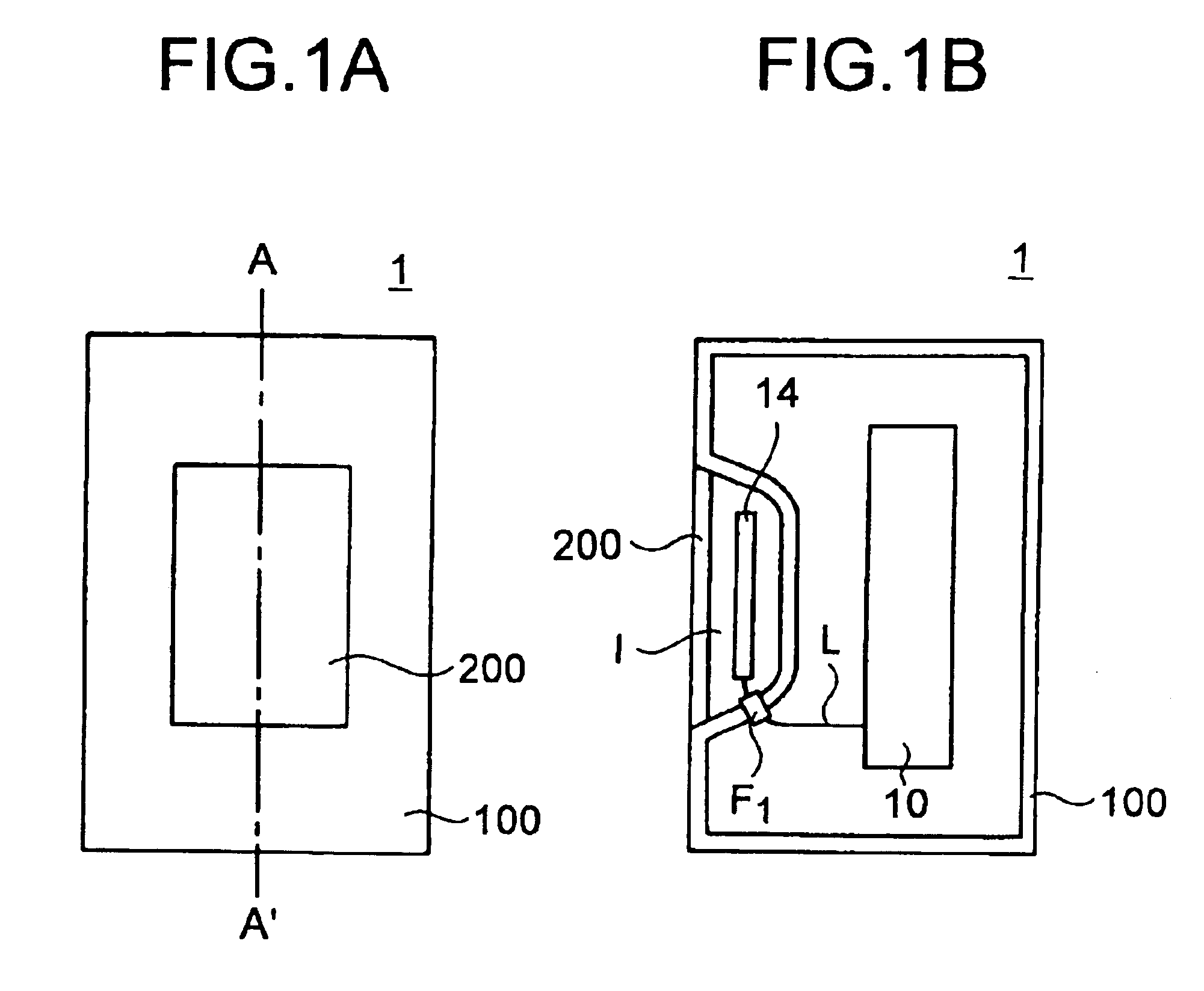
Hereinafter, embodiments of the present invention will be described with reference to the drawings. The interrogator 1 of the invention has the same configuration as that shown in FIG. 7. FIG. 1A is an external front view of this interrogator 1, and FIG. 1B is a sectional view thereof taken along line A-A′ shown in FIG. 1A. The internal circuits 10 other than the antenna 14 are enclosed in a shielding member 100 made of a material that shuts off, reflects, or absorbs (in other words, attenuates) radio waves. The shielding member is made of, for example, metal.

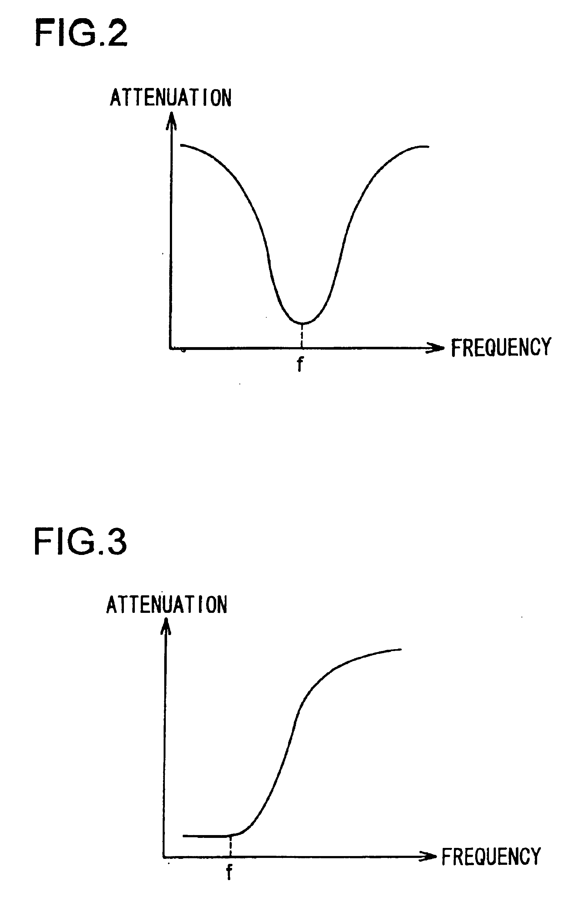
The shielding member 100 enclosing the internal circuits 10 has a recess I formed therein so as to sink inward. The antenna 14 is arranged in this recess I. In front of the antenna 14, a shielding member 200 made of a material that attenuates radio waves in a predetermined frequency band is arranged so as to cover the opening of the recess I. Thus, the antenna 14 is enclosed, at the front face thereof, by the shielding member 2...

second embodiment

The interrogator 1 of the invention has the same configuration as that shown in FIG. 7. FIG. 4A is an external front view of this interrogator 1, FIG. 4B is a sectional view thereof taken along line A-A′ shown in FIG. 4A. and FIG. 4C is a sectional view thereof taken along line B-B′ shown in FIG. 4A. The internal circuits 10 other than the antenna 14 are enclosed in a shielding member 300 made of a material that shuts off, reflects, or absorbs radio waves.

The shielding member 300 enclosing the internal circuits 10 has a recess I formed therein so as to sink inward. The antenna 14 is arranged in this recess I. In front of the antenna 14, a shielding member 400 made of a material that shuts off, reflects, or absorbs radio waves is arranged so as to cover the opening of the recess I. The shielding member 400 has four quadrilateral openings W formed in a grid-like formation in the portion thereof facing part of the front face of the antenna 14. Thus, when the interrogator 1 is viewed fr...


PUM


Abstract

In a communication device, electric circuits other than an antenna are enclosed in a shielding member made of a material that shuts off radio waves, and the antenna is enclosed by disposing in front thereof a radio wave absorbing member that attenuates radio waves in a predetermined frequency band. Thus, unnecessary electromagnetic emission is alleviated while satisfactory communication quality is secured.

Description

TECHNICAL FIELDThe present invention relates to a communication device that supplies electric power to a communication partner and communicates therewith by electromagnetic induction on a non-contact basis.BACKGROUND ARTA non-contact communication system consists of an interrogator installed in a fixed position and a responder formed in the shape of a card so as to be portable. The supply of electric power from the interrogator to the responder and the communication between the interrogator and the responder are achieved by electromagnetic induction on a non-contact basis. Thus, non-contact communication systems, having the advantages that the responder does not need to incorporate a battery and that the interrogator and the responder communicate with each other on a non-contact basis, are adopted in a variety of fields, for example in lift facilities in skiing grounds, for ticket examination in railway systems, and for baggage sorting.Now, an interrogator 1 and a responder 2 consti...

Claims


Application Information

Patent Timeline
IPC IPC(8): G06K19/07G06K19/077H01Q1/00H01Q1/52H01Q17/00H01Q1/24H01Q1/48H01Q7/00H04B1/38G06K17/00H01Q7/04H04B1/59H04B5/02
CPCH01Q1/526H01Q7/00H01Q17/001H04B1/3838G06K19/0723H01Q1/52G06K19/07771H01Q1/243H01Q1/245H01Q1/48G06K19/07749
Inventor NAGI, KATSUTOSHIUEDA, TAKASHI
Owner ROHM CO LTD
Why Eureka
Try Eureka