Seat slide device

a seat and slide technology, applied in the field of seat slide devices, can solve the problems of poor locking performance of the lock mechanism, time-consuming assembling work, and the failure of the seat slide devices of the publications to provide the makers and users with a satisfaction

Inactive Publication Date: 2005-03-22
TF METAL CO LTD
View PDF13 Cites 62 Cited by
  • Summary
  • Abstract
  • Description
  • Claims
  • Application Information

AI Technical Summary

Problems solved by technology

However, due to their inherent construction, the seat slide devices of the publications fail to provide the makers and users with a satisfaction.
That is, some of them show a poor locking performance of the lock mechanism and some of them need a troublesome and thus time-consumed assembling work for assembling the seat slide device.
Furthermore, some of them fail to provide a satisfied compact construction, and some of them are highly costly.

Method used


Image

  • Seat slide device
  • Seat slide device
  • Seat slide device

Examples


first embodiment

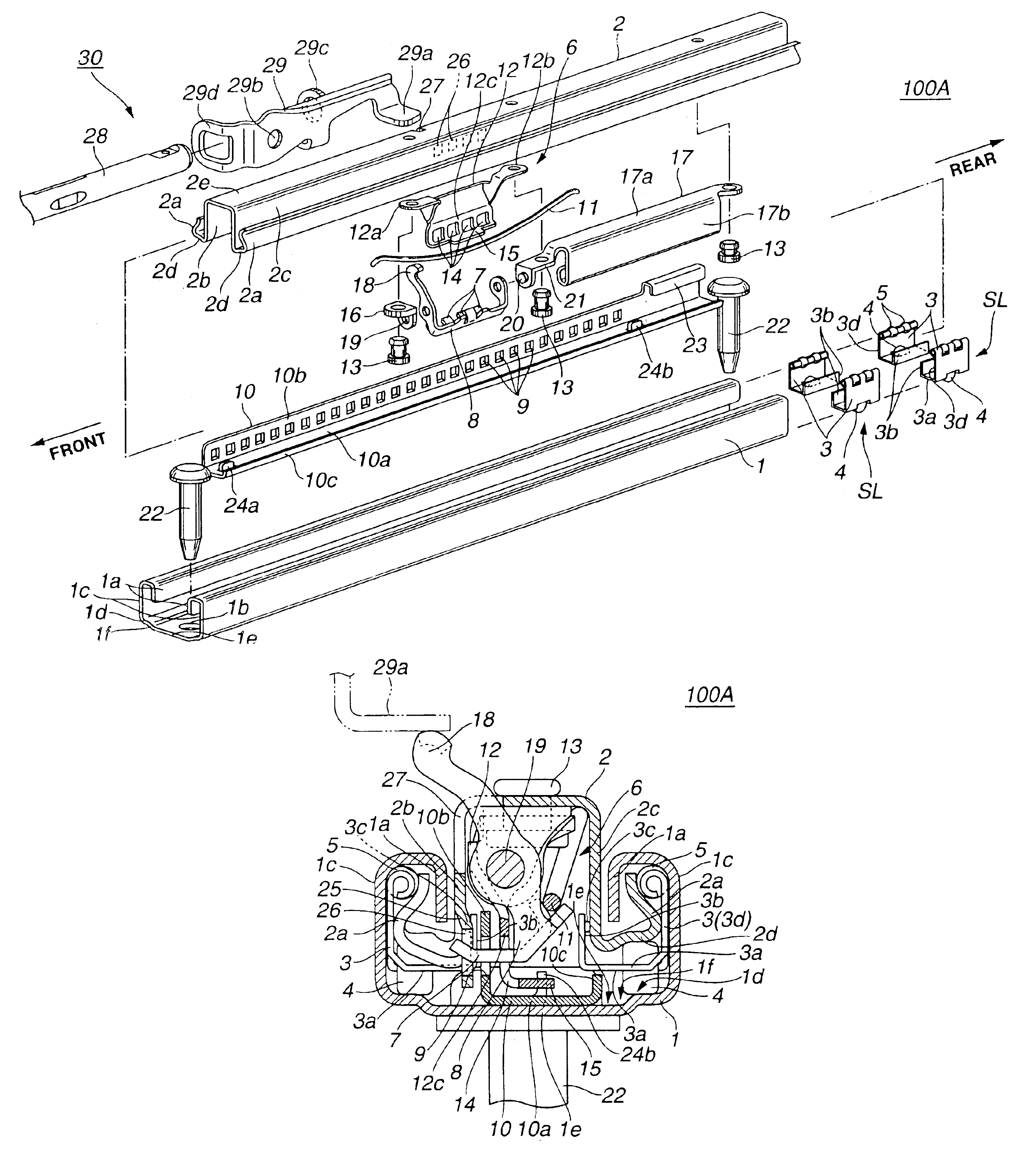
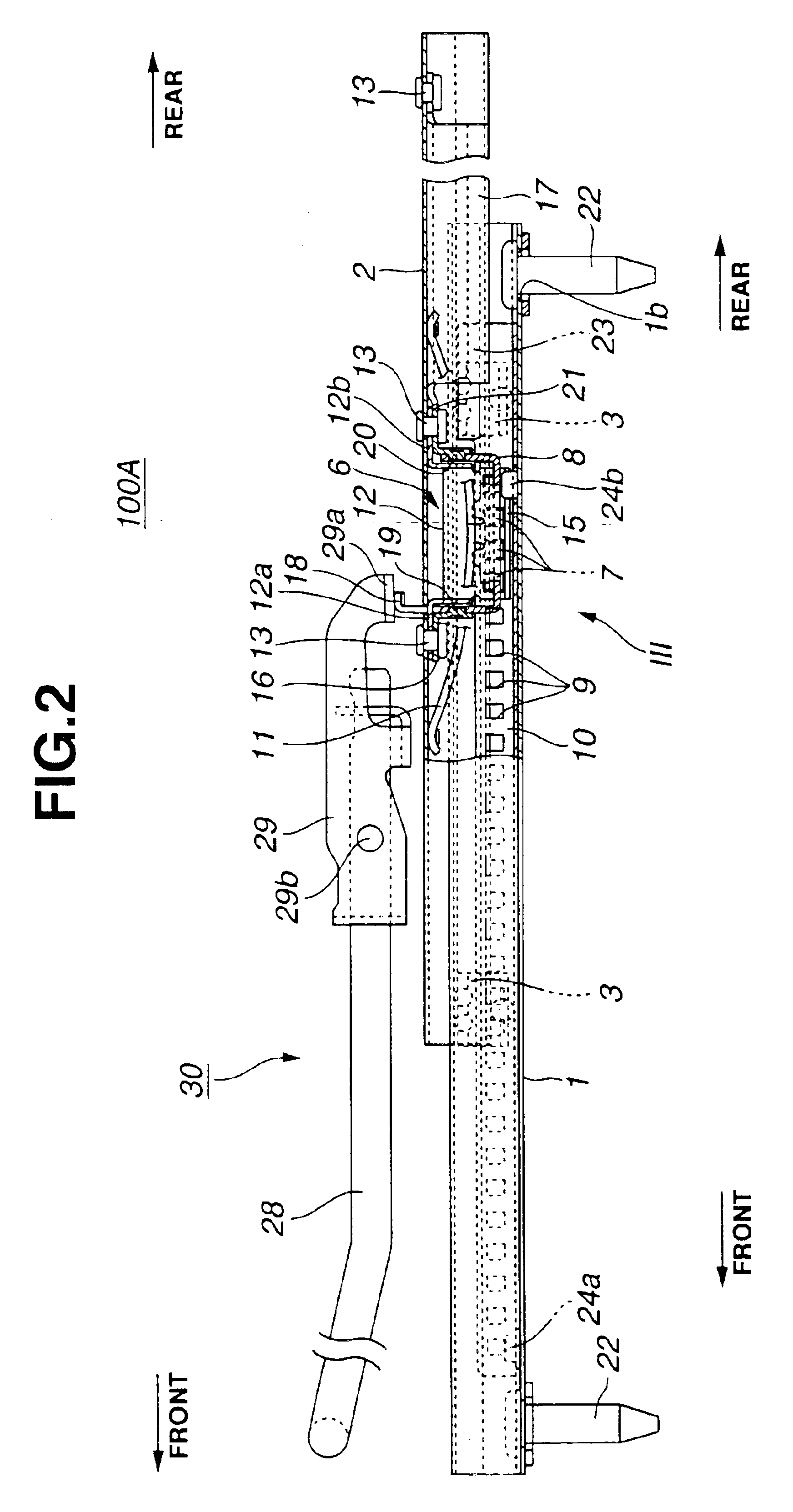
Referring to FIGS. 1 to 7, particularly FIGS. 1 to 4, there is shown a seat slide device 100A which is the present invention.

As is understood from FIGS. 1 and 2, the seat slide device 100A comprises a lower rail 1 that has a generally U-shaped cross section and is secured to a vehicle floor (not shown) by bolts 22 and an upper rail 2 that has a generally reversed U-shaped cross section and slides on and along the lower rail 1. Although not shown in the drawings, a seat (more particularly, a seat portion of the seat) is mounted on the upper rail 2, so that the seat can slide on and along the lower rail 1 together with the upper rail 2.

As will become apparent as the description proceeds, another seat slide device that is substantially the same in construction as the device 100A is arranged beside the device 100A for carrying or supporting the seat together with the device 100A.

For smoothing the movement of the upper rail 2 relative to the lower rail 1, two pairs of sliders SL are rece...

second embodiment

Referring to FIGS. 19 to 25, particularly FIGS. 19 to 22, there is shown a seat slide device 100B which is the present invention.

Since the seat slide device 100B is similar in construction to the above-mentioned seat slide device 100A of the first embodiment, the following description on the device 100B will be directed to only portions which are different from those of the first embodiment 100A.

As is well shown in FIG. 19, in the second embodiment 100B, the lock plate 10 is secured to the lower rail 1 by the bolts 22. For this securing, the elongate lower base portion 10a of the lock plate 10 has at its longitudinal ends respective bolt openings (no numerals) through which the bolts 22 pass. Each bolt 22 passes through an opening 1b formed in the lower rail 1 for tight engagement with a threaded bolt opening (not shown) formed in the vehicle floor (not shown).

Thus, as is seen from FIG. 21, the apertured end of the elongate lower base portion 10a is directly put on the apertured end...

third embodiment

Referring to FIGS. 26 to 32, particularly FIGS. 26 to 29, there is shown a seat slide device 100C which is the present invention.

Since the seat slide device 100C is similar in construction to the above-mentioned seat slide device 100B of the second embodiment, only portions which are different from those of the first embodiment 100B will be described in detail in the following.

As is seen from FIG. 26, in the third embodiment 100C, the bar spring 11 has at its middle portion two aligned projections 11a between which a depressed portion 11b is defined. For engagement with such projections 11a, the toothed portion 7 of the bridge portion of the latch lever 8 has a spring catch portion 17.

As is best seen from FIG. 28, the spring catch portion 17 comprises two aligned projections 17a between which an offset projection 17b is defined. Upon assembly, these three projections 17a and 17b of the spring catch portion 17 of the latch lever 8 neatly receive the three portions 11a and 11b of the ...


PUM


Abstract

An upper rail is slidably engaged with a lower rail in a manner to define an elongate enclosed space therebetween. A lock plate is placed in the elongate enclosed space and secured to the lower rail. A latch lever includes a pawl portion and an input arm and is placed in the elongate enclosed space. The latch lever is pivotally connected to the upper rail to pivot between a lock position where the pawl portion is engaged with a part of the lock plate to establish a locked engagement between the lower and upper rails and an unlock position where the pawl portion is released from the lock plate to cancel the locked engagement. The latch lever is pivoted in a direction from the lock position to the unlock position when the input arm is applied with an external force. A spring member is placed in the elongate enclosed space to bias the latch lever to pivot toward the lock position, An opening is formed in the upper rail for having a given part of the input arm projected outward therethrough.

Description

BACKGROUND OF THE INVENTION1. Field of the InventionThe present invention relates in general to seat slide devices for motor vehicles and more particularly to the seat slide devices of a type that has an improved lock mechanism is compact in construction.2. Description of the Related ArtHitherto, various seat slide devices have been proposed and put into practical use particularly in the field of wheeled motor vehicles. Some of them are of a type that has a lock mechanism that is compactly installed between a lower rail that is secured to a vehicle floor and an upper rail that slides on and along the lower rail and mounts thereon a seat. Seat slide devices of such type are shown in Japanese Laid-open Patent Application (Tokkaihei) 10-309965 and Japanese Laid-open Patent Application 2002-154356. However, due to their inherent construction, the seat slide devices of the publications fail to provide the makers and users with a satisfaction. That is, some of them show a poor locking per...

Claims


Application Information

Patent Timeline
Patent Type & Authority Patents(United States)
IPC IPC(8): B60N2/08B60N2/06B60N2/07
CPCB60N2/0705B60N2/0707B60N2/0843B60N2/073B60N2/0818B60N2/0715B60N2/08
Inventor MATSUMOTO, TADASHISAITOH, TAKASHIOSANAI, AKIRA
Owner TF METAL CO LTD
Why Eureka
Try Eureka