Base assembly for a sunshade

a technology for sunshade and base assembly, which is applied in the direction of mechanical equipment, machine supports, other domestic objects, etc., can solve the problems of troublesome and laborious, disengagement of adding members, etc., and achieve the effect of easy attachment/removal of additional weigh

Inactive Publication Date: 2005-03-22
TUNG BENSON
View PDF16 Cites 55 Cited by
  • Summary
  • Abstract
  • Description
  • Claims
  • Application Information

AI Technical Summary

Benefits of technology

An object of the present invention is to provide a base assembly for a sunshade which allows easy attachment / removal of additional weight to / from the base.
Another object of the present invention is to provide a base assembly for a sunshade that does not rust easily.

Problems solved by technology

However, the padding members are apt to be disengaged from the main portion 121 and thus lost.
Attachment of an additional weight to the underside of the base 12 has been proposed, yet this involves placing the bulky base 12 down to a horizontal position before attachment of the additional weight and moving the base 12 (which is now heavier) back to the upright position, which is troublesome and laborious.

Method used


Image

  • Base assembly for a sunshade
  • Base assembly for a sunshade
  • Base assembly for a sunshade

Examples


Embodiment Construction

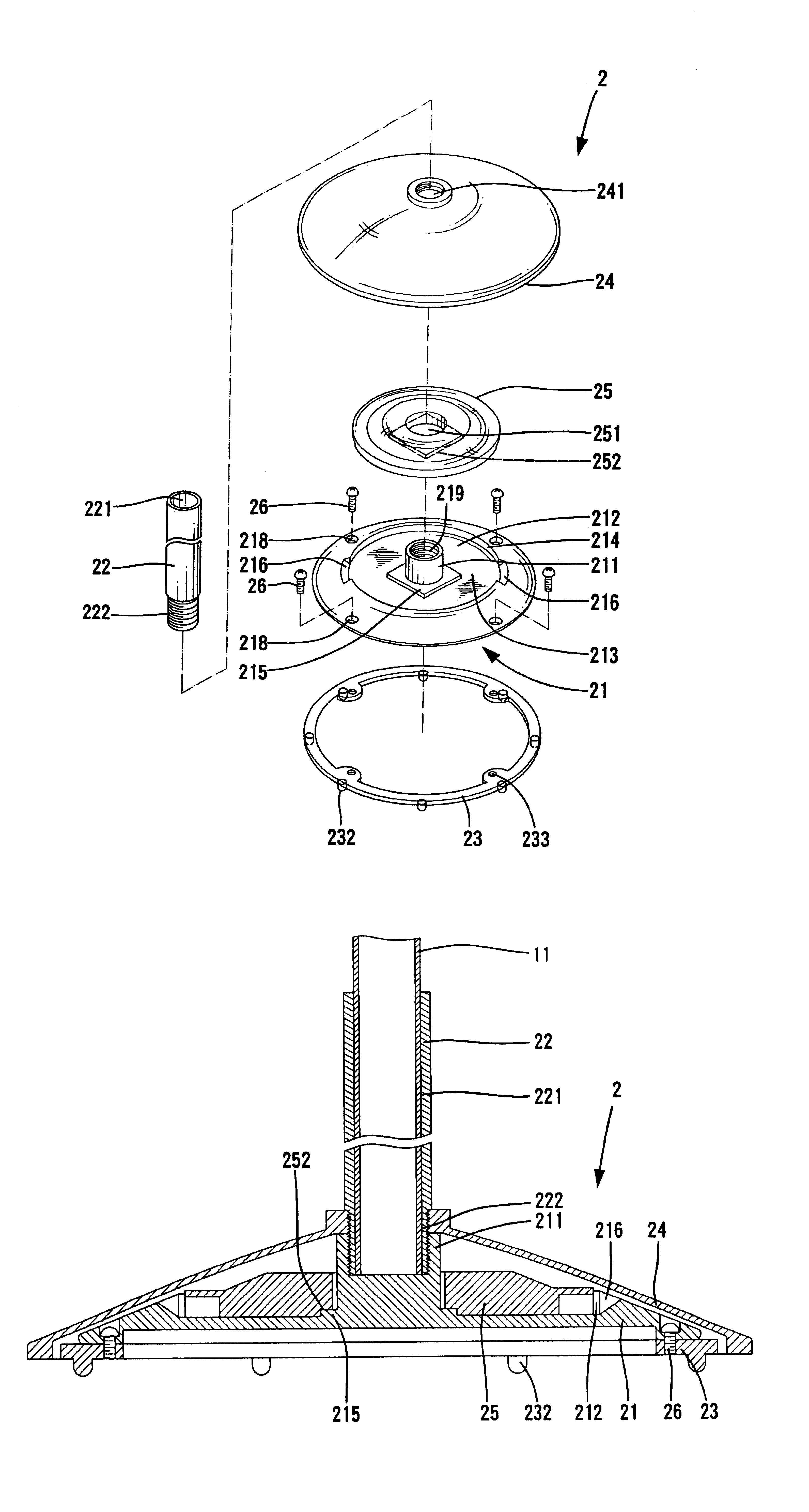
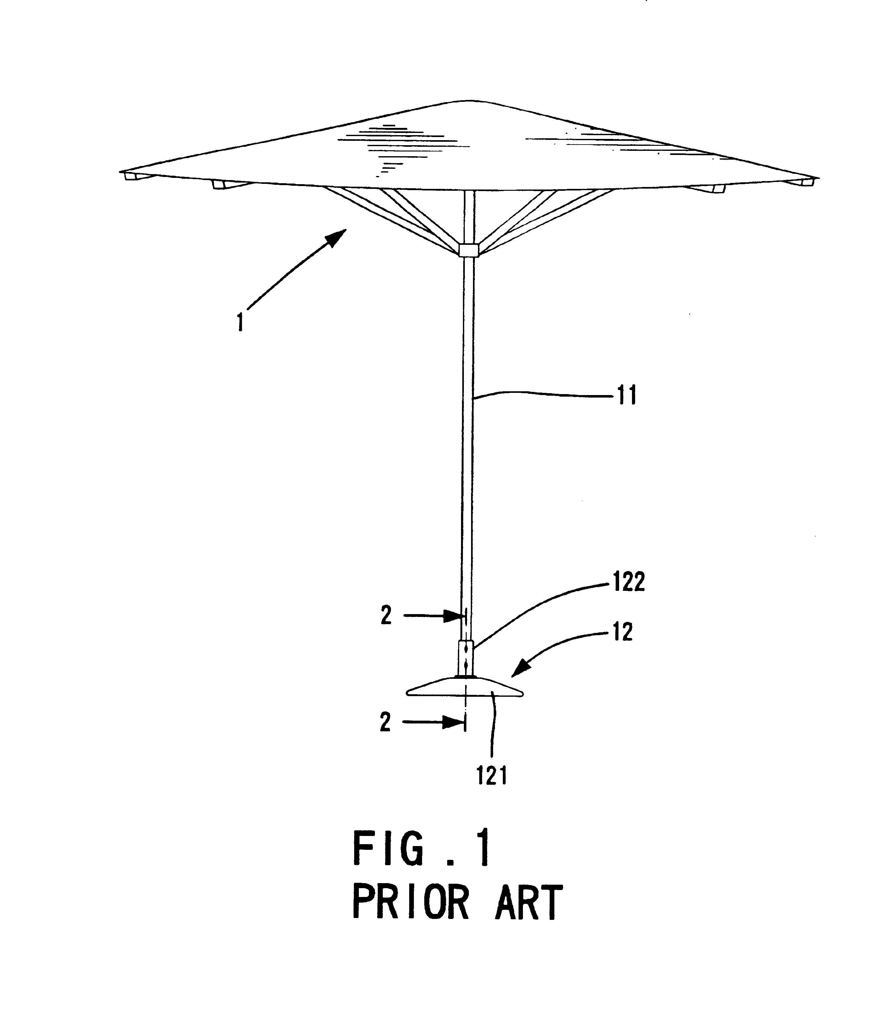
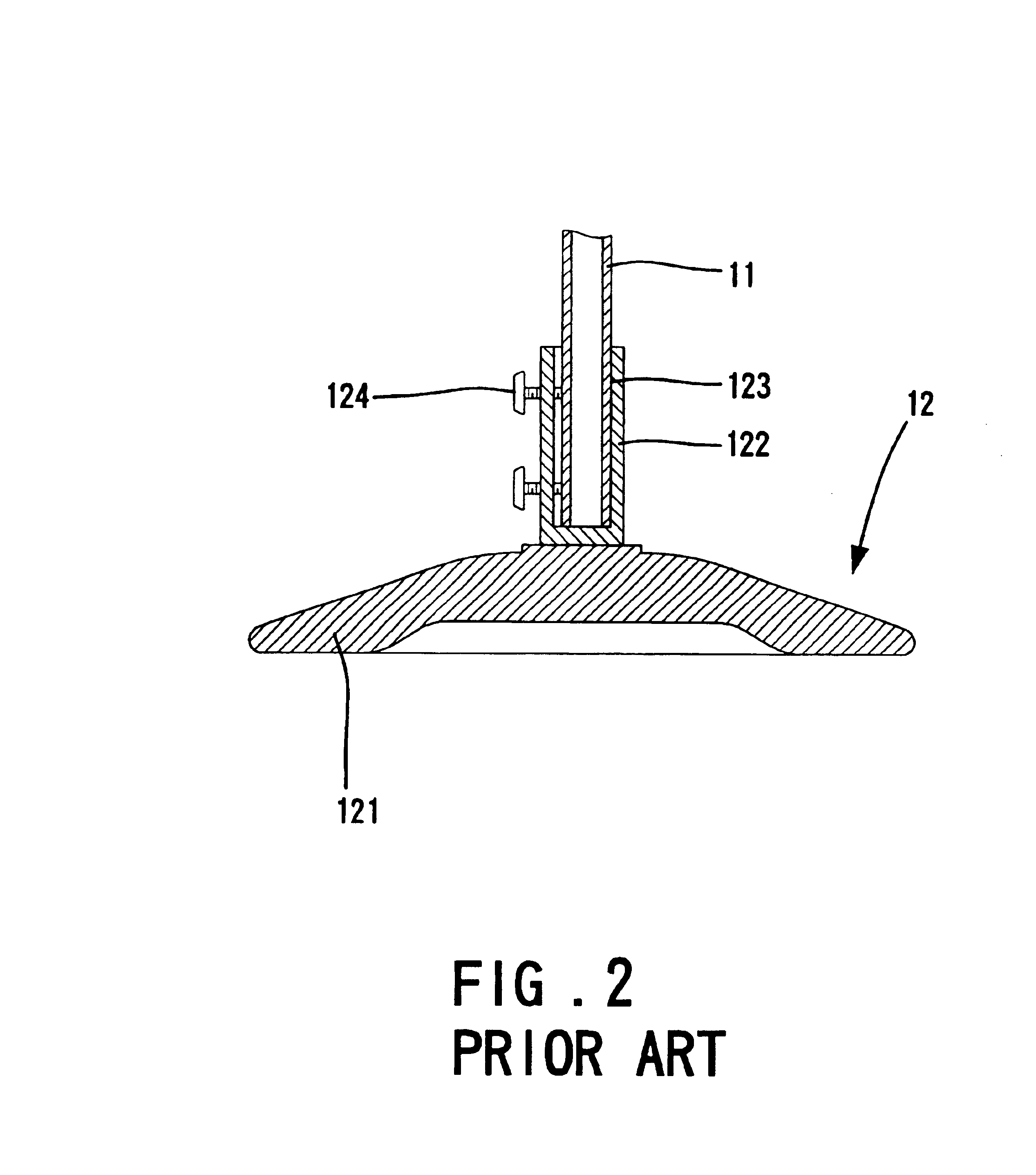
Referring to FIGS. 3 through 5, a base assembly in accordance with the present invention is designated by “2” and attached to a lower end of a post 11 of a sunshade 1. The base assembly 2 includes a base 21, a sleeve 22, and at least one weight 25. The base 21 is made of cast iron to provide a stable support for the post 11 of the sunshade 1 and includes a recessed portion 212 in an upper side thereof. The recessed portion 212 is preferably annular and concentric with the base 21. A tubular member 211 is provided on a central portion of the upper side of the base 21. The weight 25 is removably placed into the recessed portion 212. In this embodiment, the weight 25 is a disc-like member having a central hole 251 through which the tubular member 211 extends; namely, the weight 25 is mounted around the tubular member 211. Preferably, the weight 25 includes a non-circular recess 252 in an underside thereof, and a non-circular extension 215 is formed on an outer periphery of the tubular ...


PUM


Abstract

A base assembly for a sunshade includes a base having a recessed portion defined in an upper side thereof, allowing additional weight to be removably inserted into the recessed portion. The base further includes a tubular portion for receiving a lower end of a post of a sunshade. A spacer is preferably attached to an underside of the base for keeping the base at a level above ground. The tubular portion of the base may include a threaded section. A sleeve has a threaded section for threadedly engaging the threaded section of the tubular portion of the base, with the lower end of the post being received in the lower end of the sleeve.

Description

BACKGROUND OF THE INVENTION1. Field of the InventionThe present invention relates to a base assembly for a sunshade. In particular, the present invention relates to a base assembly that can be used with sunshade posts of various diameters.2. Description of the Related ArtFIG. 1 of the drawings illustrates a sunshade 1 with a conventional base 12. FIG. 2 is an enlarged sectional view of the base 12 in FIG. 1. The base 12 is attached to a lower end of a post 11 of the sunshade 1 for supporting the sunshade 1 in an upright position. The base 12 includes a main portion 121 that is a disc-like member made of cast iron and a sleeve 122 fixed on top of the main portion 121. The lower portion 123 of the post 11 is placed into the sleeve 122, and two screws 124 are extended through screw holes (not labeled) of the sleeve 122 to be in frictional contact with an outer periphery of the lower portion of the post 11. The sunshade 1 is thus kept in an upright position.Spacers (not shown) are often...

Claims


Application Information

Patent Timeline
Patent Type & Authority Patents(United States)
IPC IPC(8): E04H12/22
CPCE04H12/2238E04H12/2269Y10S248/91
Inventor TUNG, BENSON
Owner TUNG BENSON
Why Eureka
Try Eureka