Terminal load

a terminal load and load technology, applied in the direction of waveguide type devices, coupling device connections, two-part coupling devices, etc., can solve the problems of inconvenient manufacture of conventional terminal loads, affecting the quality of products, and preventing rapid mass production of conventional terminal loads b>1/b>, etc., to achieve good conductivity of terminal loads, increase productivity, and production quick

Inactive Publication Date: 2014-06-24
DIN IND
View PDF5 Cites 0 Cited by
  • Summary
  • Abstract
  • Description
  • Claims
  • Application Information

AI Technical Summary

Benefits of technology

[0007]A primary object of the present invention is to provide a terminal load that is not easily shaken and provides good conductivity during use.
[0008]Another object of the present invention is to provide a terminal load that can be quickly produced to lower the manufacturing cost thereof and avoid unnecessary waste of time and labor.
[0013]The locating surface in the insulating cylinder provides a place for stably mounting the circuit board and the notch on the rear end of the insulating cylinder engages with the rear narrowed section of the circuit board, so that the circuit board does not shake when the terminal load is in use. The conductive cap is fitly clamped around the rear end of the insulating cylinder and accordingly does not break or wear during the process of punching the terminal load into the outer housing. Further, the conductive cap provides large contact surface area to tightly contact with the barrel portion of the outer housing, ensuring good conductivity of the terminal load.
[0014]Under the protection provided by the insulating housing, the circuit board and the connection terminal mounted therein are not subjected to impact and vibration during the punching process to cause damaged parts and defective products. The configuration of the insulating housing ensures successful assembling of it to the outer housing. Since the insulating cylinder is a cylindrical body matching an inner wall surface of the barrel portion, the insulating housing is in tight contact with the outer housing after being fitted in the outer housing. This also enables quick production and increased productivity, and accordingly, lowered manufacturing cost.
[0015]In brief, the present invention is characterized by mounting the circuit board on the locating surface in the insulating cylinder, projecting the rear narrowed section of the circuit board through the notch formed on the rear end of insulating cylinder, and clamping the rearwardly projected narrowed section of the circuit board in the hole and between the contacting arms formed on the conductive cap, so that the circuit board would not shake when the terminal load is in use. The present invention is also characterized in that the conductive cap provides large contact surface area with the inner surface of the barrel portion of the outer housing, and this together with the fact that the rear narrowed section of the circuit board is clamped between the contacting arms ensure good conducting effect of the terminal load. Moreover, the insulating housing provides protection to the connection terminal and the circuit board, so that they are not damaged in the process of punching the terminal load into the barrel portion of the outer housing to cause defective products. This enables quick production of the terminal load to reduce the manufacturing cost thereof.

Problems solved by technology

Meanwhile, since the two ground surfaces 123 are so small, the conductive terminal 11 tends to have poor conductivity and results in a defective product.
Therefore, the conventional terminal load 1 does not suitable for assembling to the outer housing 20 by way of pressing, and is prevented from being quickly manufactured by mass production.
This would of course shorten the service life of the terminal load.

Method used


Image

  • Terminal load
  • Terminal load
  • Terminal load

Examples


Embodiment Construction

[0024]The present invention will now be described with a preferred embodiment thereof and with reference to the accompanying drawings.

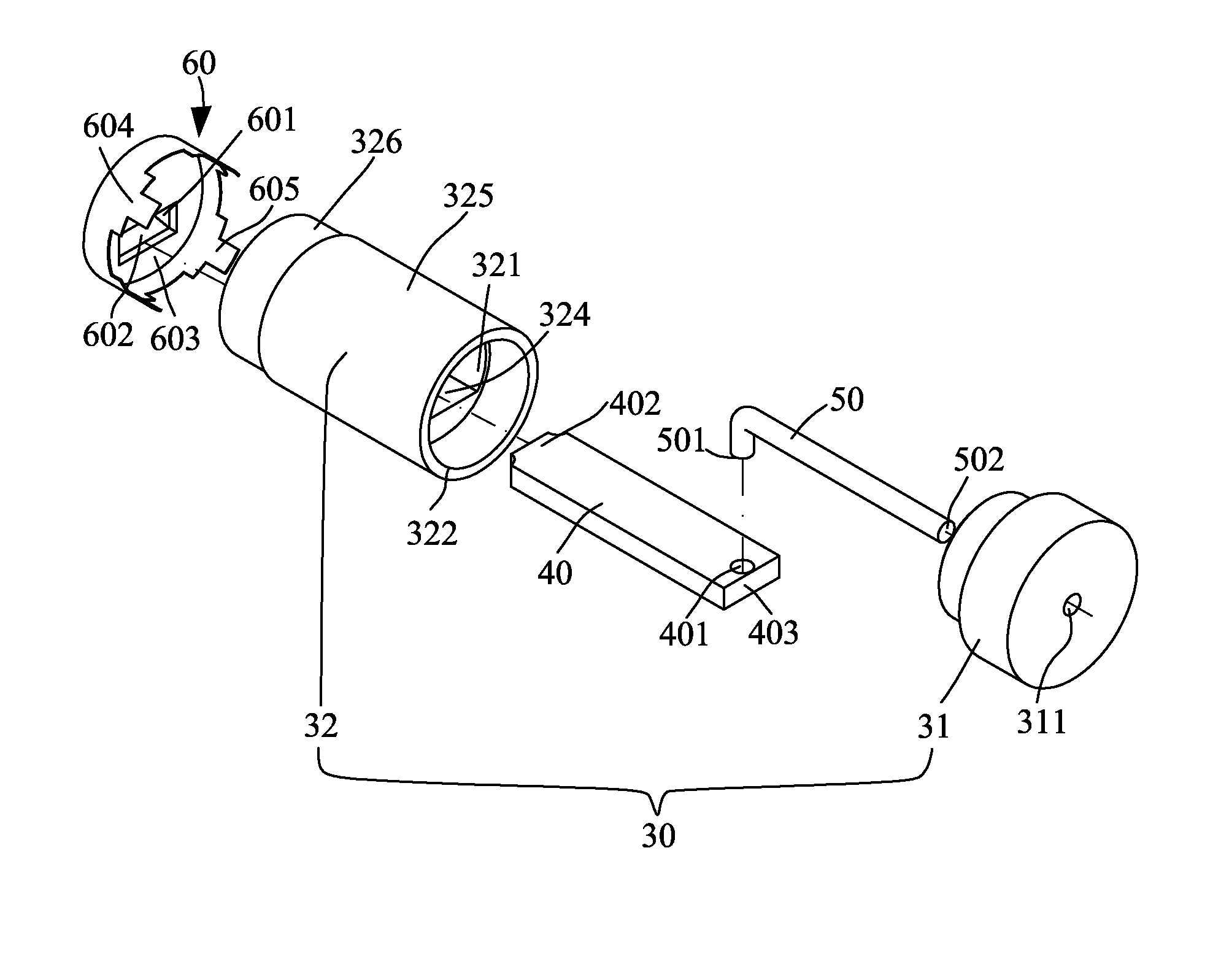
[0025]Please refer to FIG. 3. A terminal load according to a preferred embodiment of the present invention includes an insulating housing 30, a circuit board 40, a connection terminal 50 and a conductive cap 60, which are assembled together to form the terminal load.

[0026]As shown, the insulating housing 30 includes an insulating cap 31 and an insulating cylinder 32. The insulating cap 31 has a centered third hole 311. The insulating cylinder 32 internally defines a receiving space 321, a front end of which is an opening 322 and a rear end of which is formed with a notch 323. An outer circumferential surface of the insulating cylinder 32 is divided into two sections, one of which adjacent to the opening 322 has a first outer diameter 325 and another of which adjacent to the notch 323 has a second outer diameter 326, giving the insulating cylinder 32 a...


PUM


Abstract

A terminal load includes an insulating cylinder internally defining a receiving space having a locating surface, and having a front open end and a rear end provided with a notch; an insulating cap mounted to the front open end of the insulating cylinder; a circuit board mounted on the locating surface to rearwardly project a rear narrowed section from the notch; a connection terminal electrically connected with the circuit board to forward extend through the insulating cap; and a conductive cap having a top hole and fitted around the rear end of the insulating cylinder with the rear narrowed section of the circuit board extended through the top hole and clamped between two contacting arms at two opposite sides of the top hole. The terminal load with the above structure can be driven by punching to safely assemble to an outer housing, and the conductive cap ensures good conducting effect.

Description

FIELD OF THE INVENTION[0001]The present invention relates to a terminal load, and more particularly to a terminal load that ensures upgraded conductivity and stability in use and allows quick and safe assembling of it to an outer housing to achieve high productivity.BACKGROUND OF THE INVENTION[0002]Generally, coaxial cables are widely used with cable televisions for signal transmission. Coaxial cables have the advantages of large bandwidth and not easily subjected to noise and signal interference, and are therefore also used by many broadband network providers as a signal transmission medium.[0003]Please refer to FIG. 1. A conventional coaxial terminal load 1 includes a cap 10, a conductive terminal 11, and a circuit board 12. The cap 10 has a first hole 101. The conductive terminal 11 has a front end forward extended through and projected from the first hole 101, and a rear end engaged with a second hole 121 formed on a front end of the circuit board 12 to electrically connect the ...

Claims


Application Information

Patent Timeline
Patent Type & Authority Patents(United States)
IPC IPC(8): H01R9/05
CPCH01R24/44H01P1/266H01R13/6658
Inventor HUANG, CHING, KUN
Owner DIN IND
Why Eureka
Try Eureka